34 H-S81-HS Installation & Operation Manual — P/N LS10114-000HI-E:A 2/24/2015
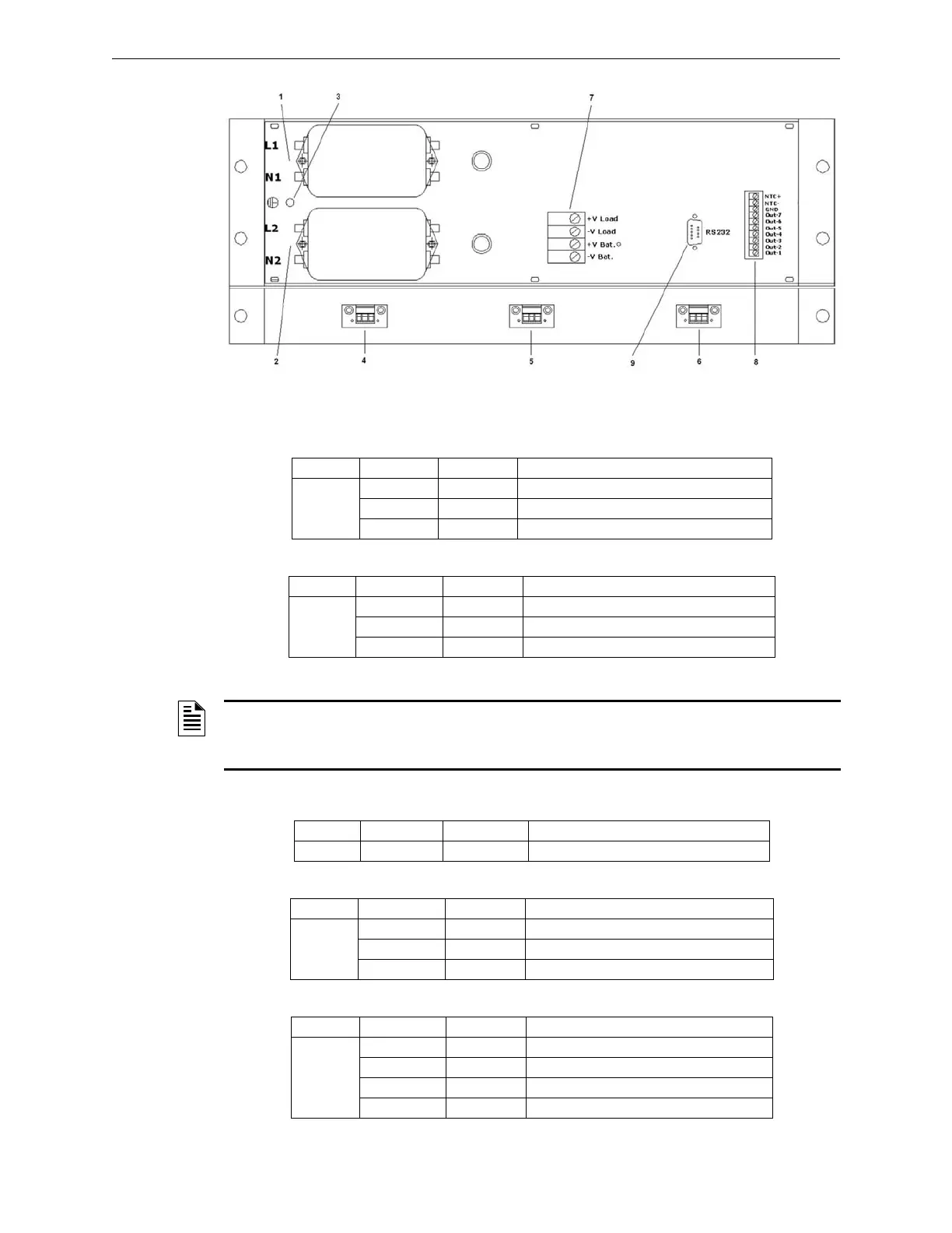
Parts of the H-S81-HS System Power Supply Set
Internal connections
Line- 1 input voltage
Line- 2 input voltage
Main earth
Cooling fans
Output voltage
Tag Faston Name Function
1
F1 L1 Primary power supply 1 phase
F2 N1 Primary power supply 1 neutral
F3 PE1 Primary power supply 1 earth
Tag Terminal Name Function
2
F1 L2 Primary power supply 2 phase
F2 N2 Primary power supply 2 neutral
F3 PE2 Primary power supply 2 earth
Figure 2.5 S81-PU002 Power Supply Set Connections
NOTE: The PU-A0008-1 modules installed in slot 2 and 3 are connected to line 1
network input. The PU-A0008-1 modules installed in slot 4 and 5 are connected to line 2
network input.
Tag Screw Name Function
3 V1 PE Rack earthing
Tag Terminal Name Function
4-5-6
M1 S Fan speedometer signal
M2 -V Fan power supply negative
M3 +V Fan power supply positive
Tag Terminal Name Function
7
M1 +VLOAD Supply voltage positive
M2 -VLOAD Supply voltage negative
M3 +VBAT Battery positive
M4 -VBAT Battery negative
 Loading...


