62 H-S81-HS Installation & Operation Manual — P/N LS10114-000HI-E:A 2/24/2015
Parts of the H-S81-HS System I/O modules
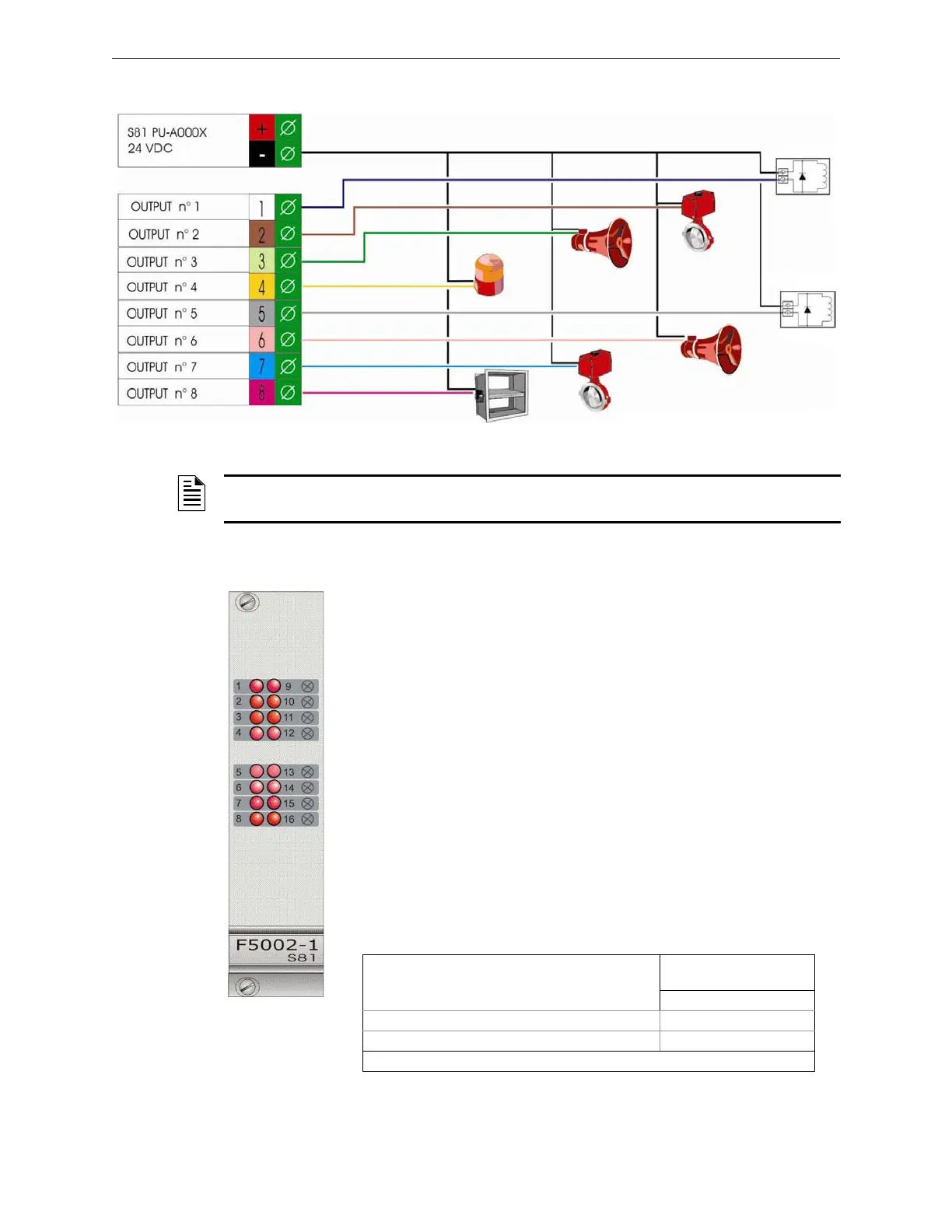
Standard Connection Diagrams
2.4.6 S81-F5002-1
Description
Module with sixteen non monitored 250mA open collector outputs. It is also
used together with the S81-T8007-2 16-relay module.
Technical Features
Status Indications
Each one of the sixteen channels on the front panel includes a status LED.
Figure 2.28 Standard Connection Diagram
NOTE: The module can control resistive or inductive loads with a maximum current of 500mA. If
the module is used for controlling filament lamps, the maximum load power cannot exceed 4W.
• Redundancy: No
• Channel test: No
• Max. output current 250mA
• Automatic output protection No
• Supply voltage: 22-29VDC
• Quiescent current: 10mA
• Operating temperature: -5 - 50 °C
• Storage temperature: -30 - 80 °C
• Maximum humidity: 95% (RH) non-condensing
• Hot swap capability: yes
Output Channel Status
Indications 1-16
Out LEDs
RED LED
Channel under normal condition −
Enabled channel ⊗
⊗= steady on LED; − = LED off
 Loading...


