H-S81-HS Installation & Operation Manual — P/N LS10114-000HI-E:A 2/24/2015 41
Central Unit Rack Parts of the H-S81-HS System
Technical features
Status Indications
The front panel includes 14 LEDs with the following functions:
Module rear panel includes 5 LEDs with the following functions:
Buttons
• Supply voltage: 22-29VDC
• Quiescent current: 70mA
• Operating temperature: -5 - 50 °C
• Storage temperature: -30 - 80 °C
• Maximum humidity: 95% (RH) non-condensing
• LCD resolution: 320 x 128 pixels
• Backlighting: LED
• Hot swap capability: yes
LED Mode Indication
Alarm (Red)
∅ Non acknowledged alarm condition
⊗ Acknowledged alarm condition
General Trouble (Yellow) ∅ General trouble condition
Device Trouble (Yellow) ∅ Sensors/actuators trouble
Sounder Trouble (Yellow) ∅ Alarm sounder trouble
PSU1 Trouble (Yellow) ∅ Primary power supply trouble
PSU2 Trouble (Yellow) ∅ Secondary power supply trouble
Ground Fault (Yellow) ∅ Earth leakage
System Trouble (Yellow) ∅ System trouble
Zone Testing (Yellow) ∅ Ongoing zone test
General disable (Yellow) ⊗ General disable condition
Device disable (Yellow) ⊗ Disabled sensors/actuators
Sounder disable (Yellow) ⊗ Disabled alarm sounder
Output Delay (Yellow) ⊗ Activation delay timer on
Voltage detection (Green) ⊗ Primary voltage detection
∅ = flashing ⊗ = steady on
LED Indication
LD15 (Yellow) Currently not used
LD16 (Yellow) Currently not used
CPU-A Link (Green) Steady on when the communication Link with CPU-A is present
CPU-B Link (Green) Steady on when the communication Link with CPU-B is present
S81-T8004-1 Link Steady on when the communication Link with S81-T8004-1 is present
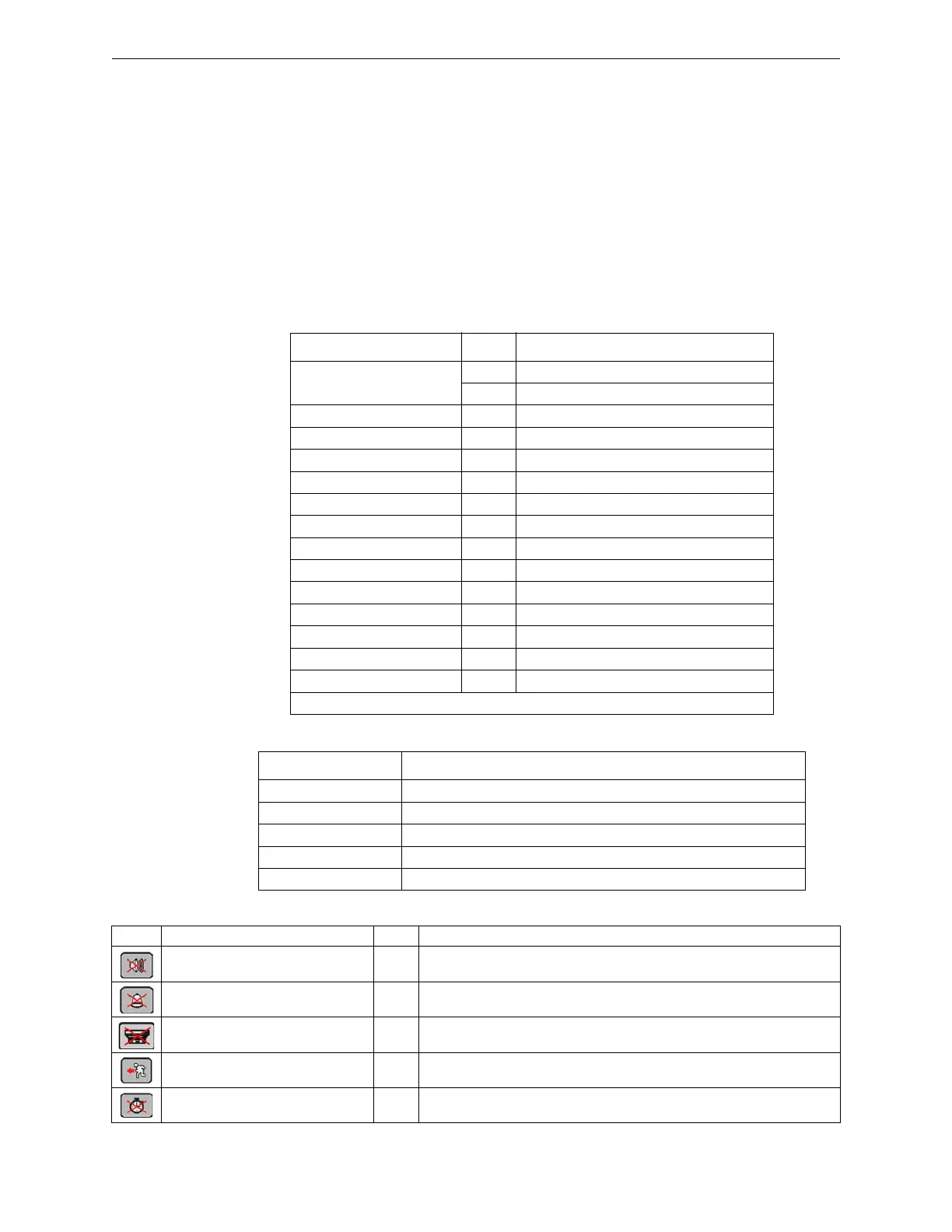
Button Description of buttons Level Description of the function
Local Buzzer Silencing 1-2-3 Deactivates the local buzzer
System sounder silencing 2-3 Silencing of system fire alarm sounders
Control panel reset 2-3 Resets the control panel
Evacuation command 2-3 Activates system fire alarm sounders
Delay time reset 1-2-3 Cancels output delay timer
 Loading...


