H-S81-HS Installation & Operation Manual — P/N LS10114-000HI-E:A 2/24/2015 39
Central Unit Rack Parts of the H-S81-HS System
J4 & J5: Printer/Debug / Host Computer
Two connectors for 10-pole flat cable, allowing the connection of a 40 or 80 column serial printer
and of a PC for configuration data transfer. Use the S81-CFT10/2 cable for connecting to the PC.
J6: Display
A connector for 20-pole flat cable, allowing the connection to the S81-U1006 display module.
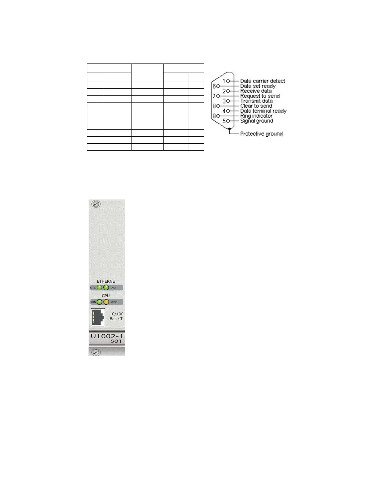
2.2.2 S81-U1002-1
Description
This module is system central unit. Besides the micro-controller, the module
includes the following elements: Flash memory, buffered static Ram, watchdog
circuit and Ethernet controller. The CPU module can be used in both single and
redundant configuration. In this last case, two CPUs operating in parallel are
used. Both CPUs process the information received from the modules, but only
one of the two CPUs runs the commands. In case of failure of the primary CPU,
the other one keeps on carrying out all the tasks without any interruption of the
machine cycle.
Technical Features
J4 Connector
Direction
DB9 Female
Pin Signal Signal Pin
1DTR DCD 1
3TXD RXD 2
5RXD TXD 3
7 DCD DTR 4
9GND GND 5
2DTR DSR 6
4CTS RTS 7
6RTS CTS 8
8RI9
10 NU
Figure 2.9 RS232 Connections
• Safety rating: applicable up to SIL3
• Micro-controller: Renesas H8-2318 at 25Mhz
• RAM memory: 4 MB, lithium battery buffered
• FLASH memory: 2 MB
• Ethernet Output: 10/100BaseT with RJ45 connector
• Watch Dog: external
• Redundancy YES
• Supply voltage: 22-29VDC
• Quiescent current: 70mA
• Operating temperature: -5 - 50 °C
• Storage temperature: -30 - 80 °C
• Maximum humidity: 95% (RH) non-condensing
• Hot swap capability: yes
 Loading...


