108 H-S81-HS Installation & Operation Manual — P/N LS10114-000HI-E:A 2/24/2015
Installation Layout of H-S81-HS/2R Internal Parts
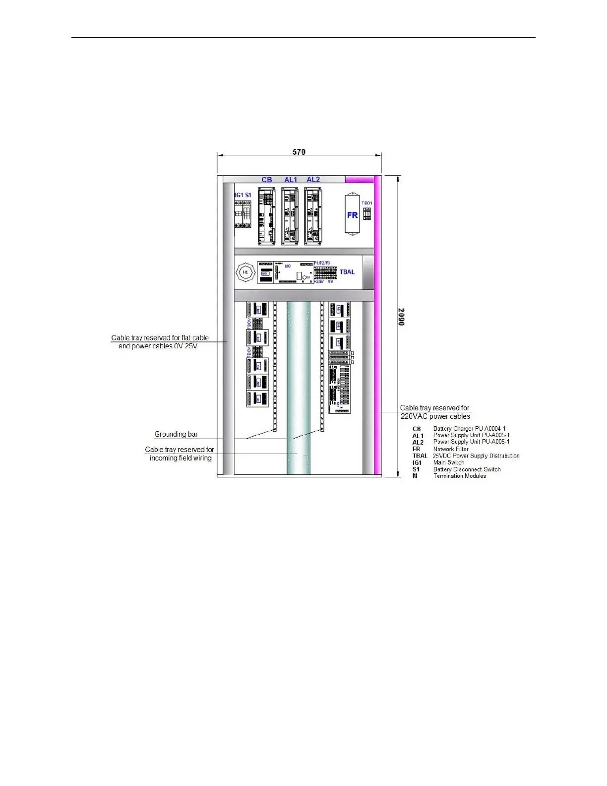
3.6 Layout of H-S81-HS/2R Internal Parts
The picture below shows the typical layout of the parts located on the base plate of H-S81-HS/2R
type control panels. In this specific configuration, field device cables are connected to I/O modules
with termination modules or multi-conductor cables. Gray cable conduits are only for cables con-
necting I/Os to termination modules. The light blue cable tray instead is only for cables coming
from field devices, whereas the magenta cable tray is for the main supply cable only.
Figure 3.5 H-S81-HS/2R Internal Plate
 Loading...


