H-S81-HS Installation & Operation Manual — P/N LS10114-000HI-E:A 2/24/2015 29
Power Supply Set Parts of the H-S81-HS System
Internal Connections
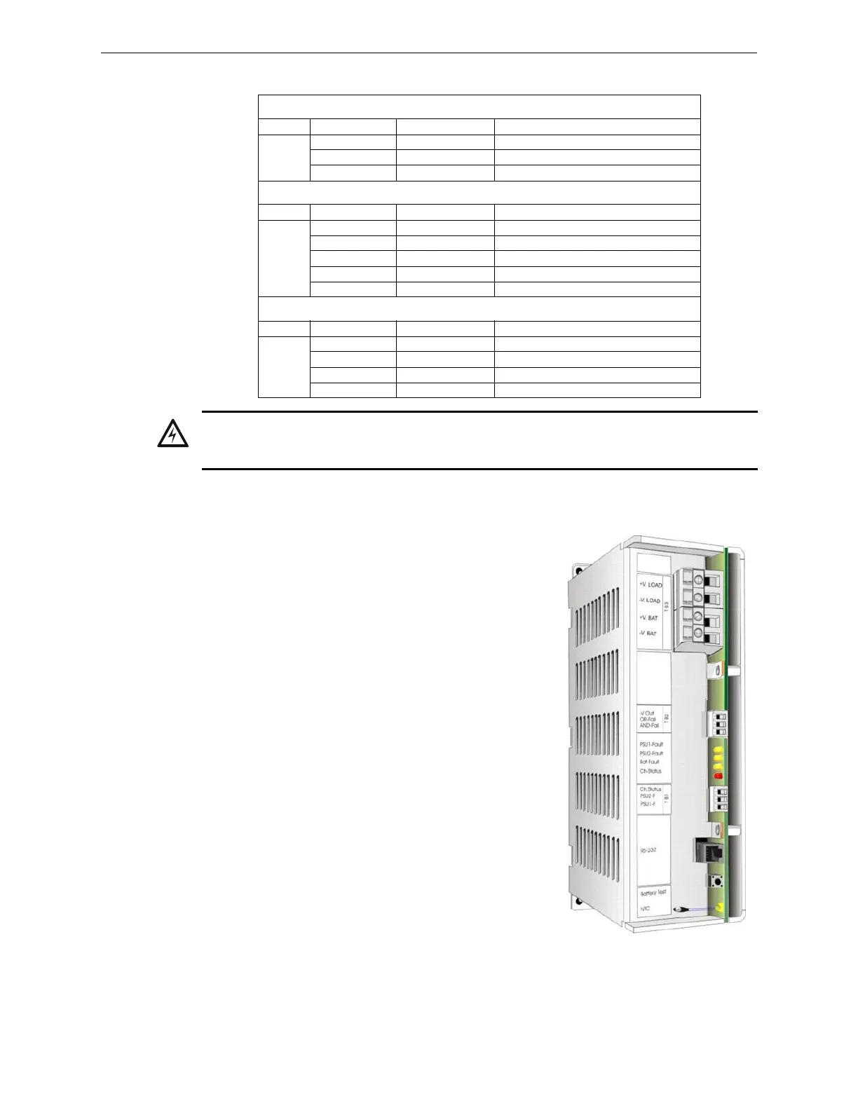
2.1.3 PU-A0004-1 Battery Charger Module
This is a UPS able to control and charge two 12 Volt batteries with a maximum
capacity of 65Ah. Battery maximum charge current can be set through a dip-
switch on the module. Under normal operating conditions, a simplified test is
carried out every 30 seconds in order to check the proper presence of the batter-
ies. A full test, instead, is carried out every hour in order to check electrical con-
nections and battery efficiency. During battery trickle charge, battery voltage is
compensated automatically according to the temperature. In case of mains volt-
age failure, batteries are automatically switched to the load without any interrup-
tions. Should the full charge stage exceed 24 hours, the power supply unit will
signal a battery fault. In case of primary power supply failure, the system will
shut batteries down when the on-load voltage is lower than 18VDC in order to
avoid damaging the batteries. The set features three open collector outputs for
replicating the faults to the alarm control panel, two inputs for monitoring the
power supply units and one RS232 port for the connection to a supervisory sys-
tem. It can be used together with one or more PU-A0005-1 power supply units.
In this case, the resulting power supply set will be fully compliant with the
EN54-4:1997/A2:2006 standard.
INPUT POWER SUPPLY CONNECTIONS
Tag. Terminal Name Function
TB1
M1 L input Phase (protected by internal fuse)
M2 N input Neutral
M3 PE Earth
CURRENT SHARE AND STATUS REPLICATION CONNECTIONS
Tag. Terminal Name Function
TB2
M1 RL-COM1 Status relay 1 common
M2 RL-NO1 Status relay 1 NO
M3 RL-COM2 Status relay 2 common
M4 RL-NO2 Status relay 2 NO
M5 SHARE (+) Signal for load distribution
OUTPUT POWER SUPPLY CONNECTIONS
Tag. Terminal Name Function
TB3
M1 - V. OUT Output voltage negative
M2 - V. OUT Output voltage negative
M3 +V. OUT Output voltage positive
M4 +V. OUT Output voltage positive
WARNING: HIGH VOLTAGE
THIS MODULE INCLUDES CIRCUITS WITH VOLTAGE AND CURRENT VALUES POTENTIALLY
DANGEROUS FOR PEOPLE.
 Loading...


