H-S81-HS Installation & Operation Manual — P/N LS10114-000HI-E:A 2/24/2015 51
I/O modules Parts of the H-S81-HS System
Zero Point Calibration
Calibrate the zero point as reported below:
• Disable the channel of the module to be calibrated from the operator cycle.
• Enter the diagnosis cycle of the module to be calibrated.
• Make sure that no gas is present near the sensor to be calibrated.
• Press the “1” key to calibrate the zero point.
• The new zero value is stored in the memory of the module.
• Press “0” to cancel the operation.
• Exit the module diagnosis cycle and enable the channel.
End of Scale Calibration
Calibrate the end of scale as follows:
• Disable the channel of the module to be calibrated from the operator cycle.
• Enter the diagnosis cycle of the module to be calibrated.
• Apply gas to the sensor according to the percentage set during configuration.
• Wait for the gas value measured by the module to stabilize.
• Press the key “3” to calibrate the end of scale.
• The new value is stored in the memory of the module.
• Press “2” to cancel the operation.
• Exit the module diagnosis cycle and enable the channel.
Field Connections
The module can be connected to field terminal block by using a flat or a multi-conductor cable,
depending on the used bus type.
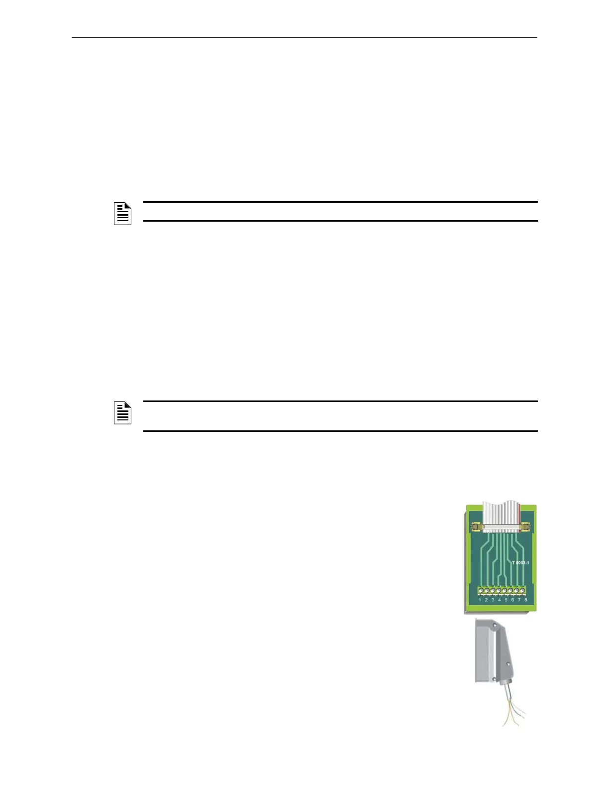
S81-E2001-1 Bus
The module is connected to a S81-T8003-1 termination module with 8 termi-
nals with a 20-way flat cable.
S81-E2001-2 Bus
The module is connected to the field terminal block with the S81-CCT2 16-
conductor multi-polar cable. For S81-F4001-2 module redundant connection,
use the S81-CCT2R cable.
NOTE: The zero point can be calibrated only with zero values ranging between 3 and 5mA.
NOTE: The end of scale can be calibrated only if the current value measured by the module is
±3mA than the set calibration value.
 Loading...


