112 H-S81-HS Installation & Operation Manual — P/N LS10114-000HI-E:A 2/24/2015
Installation Instructions for the Connection of Field Devices
3.12.3 Addressable Loop Cables
For these types of signal we recommend using shielded twisted pair cables CEI EN 50200 2 x 1
mm
2
. Cable section depends on the length, and on the number and type of installed devices. How-
ever, total cable resistance must not exceed 40 Ohms, cable capacity must be below 1 µF and
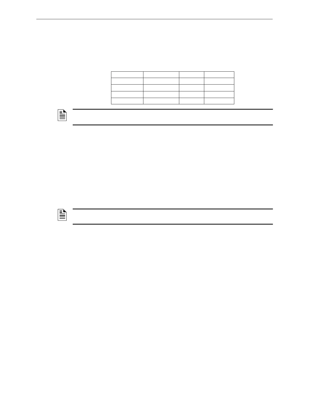
inductance below 1 mH. The table below shows the minimum cable section required according to
loop length.
3.12.4 25 VDC Power Cables
For control panel to field device power supply, we recommend using shielded twisted pair cables
CEI EN 50200 2 x 1 mm
2
. Please take utmost care when selecting the conductors to avoid that the
voltage drop along the cable may prevent the connected devices from operating.
3.12.5 Output Cables
For the connection between control panel and outputs (sounders, solenoid valves, panels) we rec-
ommend using flame-resistant, shielded twisted pair cables CEI EN 50200. Also in this case, check
the voltage drop on the cable and increase its section, if necessary.
Loop Length Type of Cable AWG Type
≤ 1000 meters 2 x 1 mm
2
16AWG Belden 9575
≤ 1500 meters 2 x 1.5 mm
2
16AWG Belden 9575
≤ 2000 meters 2 x 2.5 mm
2
14AWG Belden 9581
≤ 3000 meters 2 x 4 mm
2
12AWG Belden 9583
NOTE: In case of closed loops, cable length is the overall length from starting to end point. Multi-
conductor cables cannot be used for loop connection.
NOTE: Use the relay contacts on S81-T8006 and S81-T8007 relay termination modules only
with Safety Extra Low Voltages.
 Loading...


