H-S81-HS Installation & Operation Manual — P/N LS10114-000HI-E:A 2/24/2015 59
I/O modules Parts of the H-S81-HS System
S81-E2001-1 Bus
The module is connected to a S81-T8003-1 termination module with 8 termi-
nals with a 20-way flat cable.
S81-E2001-2 Bus
The module is connected to the field terminal block by the S81-CCT3 16-con-
ductor multi-polar cable. For S81-F4003-2 module redundant connection, use
the S81-CCT3R1 cable.
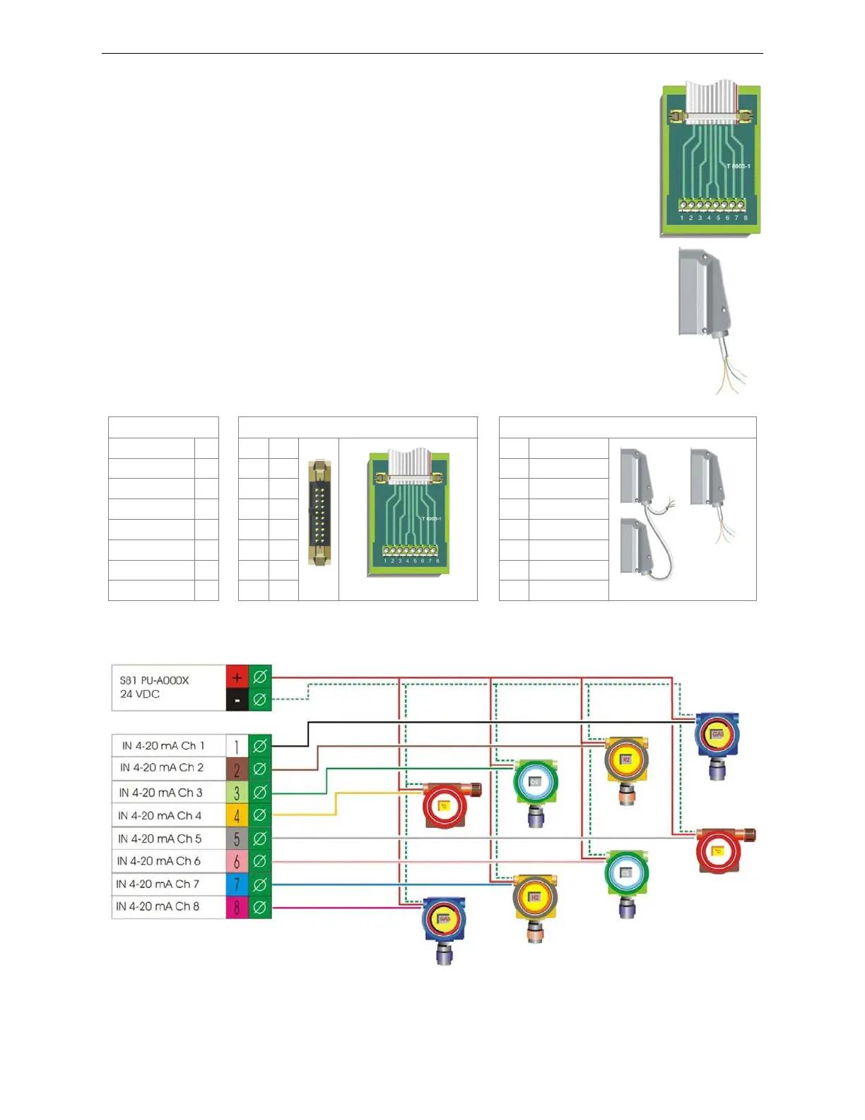
Standard Connection Diagrams
Function Termination with Flat Cable Termination with Multi-conductor Cable
Input signal 1 + ∅ 1
S81-T8003-1
1
White
S81/CCT3R
Input signal 2 + ∅ 22
Brown
Input signal 3 + ∅ 33
Green
Input signal 4 + ∅ 44
Yellow
Input signal 5 + ∅ 55
Gray
Input signal 6 + ∅ 66
Pink
Input signal 7 + ∅ 77
Blue
Input signal 8 + ∅ 88
Red
Figure 2.25 Field Connections
Figure 2.26 Standard Connection Diagram
 Loading...


