H-S81-HS Installation & Operation Manual — P/N LS10114-000HI-E:A 2/24/2015 87
I/O modules Parts of the H-S81-HS System
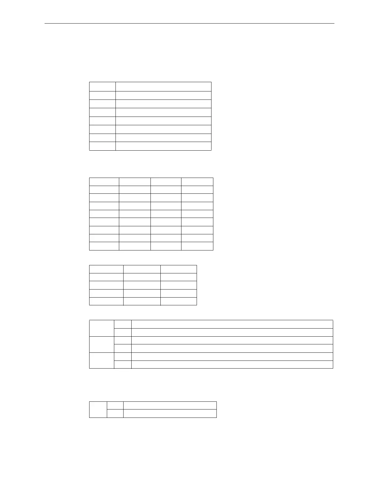
The module includes 2 x 8-way dip switches required for setting the communication parameters.
SW1: Modbus Address Configuration
SW1 dip switch configures module Modbus address in the 1-255 range. In Slave mode, it defines
module Modbus address, whereas in master mode it defines the address of the Slave peripheral
devices to which commands are to be sent. The address 00 is not allowed.
SW2: Modbus Parameter Configuration
The 1-2-3 dips of SW2 switch configure the Baud rate according to the table below:
The 4-5 dips of the SW2 switch configure parity and stop bit number
The 6-7-8 dips of the SW2 switch configure the following options:
Moreover, the module includes a Jumper for allowing the 120 ohm termination resistor on the
RS485 line.
Field Connections
The module can be connected to field terminal block by using a flat or a multi-conductor cable,
depending on the used bus type.
SW1-1 Modbus address Weight 1 (on = Active)
SW1-2 Modbus address Weight 2 (on = Active)
SW1-3 Modbus address Weight 4 (on = Active)
SW1-4 Modbus address Weight 8 (on = Active)
SW1-5 Modbus address Weight 16 (on = Active)
SW1-6 Modbus address Weight 32 (on = Active)
SW1-7 Modbus address Weight 64 (on = Active)
SW1-8 Modbus address Weight 128 (on = Active)
SW2-1 SW2-2 SW2-3 Baud Rate
Off Off Off 1200
On Off Off 2400
Off On Off 4800
On On Off 9600
Off Off On 19200
On Off On 38400
Off On On 57600
On On On 115200
SW2-4 SW2-5 Parity
Off Off No parity
On Off Even
Off On Odd
On On Not allowed
SW2-6
On 2 stop bits
Off 1 stop bit
SW2-7
On Module in Master mode
Off Module in Slave mode
SW2-8
On Freezes the last acquired status in case of Slave disconnection
1
1 Only for Master mode
Off Puts all entities in communication fault trouble condition in case of Slave disconnection
1
JP1
On RS485 primary line termination added
Off RS485 primary line termination removed
 Loading...


