H-S81-HS Installation & Operation Manual — P/N LS10114-000HI-E:A 2/24/2015 33
Power Supply Set Parts of the H-S81-HS System
Possible Configurations
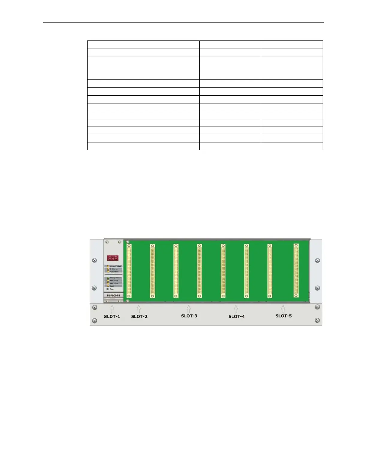
2.1.5 PU-A0007-1 Drawer with Slots
Description
It is a 19 inch rack that can contain a PU-A0009-1 battery charger module and up to four
PU-A0008-1 power supply modules. It features ventilation, consisting in three fans with a diameter
of 120 mm. The terminal blocks for power supply and status replication connection are located on
slot back.
Features S81-PU002-2 S81-PU002-4
Number of PU-A0008-1 power supply units 2 4
Power supply voltage 110-240V~ 110-240V~
Rated frequency 50-60Hz 50-60Hz
Max. input current at 110V~ 6A 12A
Max. input current at 240V~ 2.7A 5.25A
Nominal output voltage 25VDC ±2% 25VDC ±2%
Max. residual ripple <115mV <115mV
Minimum output voltage
1
1 Full load output voltage with low batteries in case of mains voltage failure
18.9VDC 18.9VDC
Min. output current
2
2 Current for the loads plus the current required by the control panel
8A duplicated 20A duplicated
Max. output current
2
12A duplicated 32A duplicated
Maximum battery resistance
3
3 Internal resistance of batteries and relevant circuits. (Cables, terminals, fuses, etc.)
0.1 Ω 0.05 Ω
Max. battery current 6A 6A
Maximum battery capacity 2x12V 120Ah 2x12V 120Ah
Figure 2.4 S81-PU002 Power Supply Set Slot
 Loading...


