H-S81-HS Installation & Operation Manual — P/N LS10114-000HI-E:A 2/24/2015 97
Termination modules Parts of the H-S81-HS System
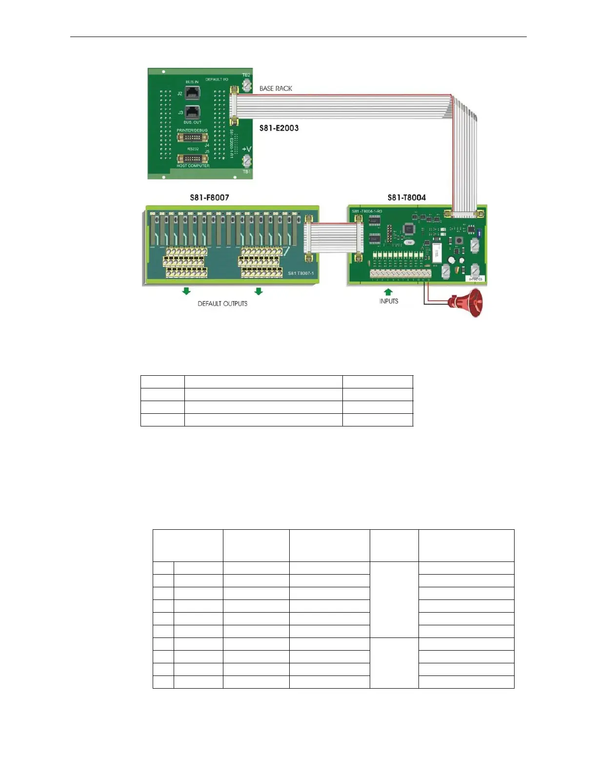
Internal Connections
TB1-TB2-TB3 Power supply
These three Faston connectors are used to connect supply voltage and earth.
J1 to J1 on S81-E2003-1
It is a connector for 14-pole flat cable, allowing connection to the S81-E2003-1 Bus module. Con-
nect using S81-CFT14/2 cable.
J2 to J1 on S81-T8001-1, J1 on S81-T8007-1 or J1 on S81-T8007-2
It is a connector for 20-pole flat cable, allowing connection to the S81-T8001-1 termination module
or to the 16-relay modules S81-T8007-1 and S81-T8007-2. Connect using S81-CFT20/05 cable.
TAG Function Cable Color
TB1 25VDC power supply positive Red
TB2 25VDC power supply negative Black
TB3 Earth Yellow/Green
Terminals
S81-T8001-1
Relay
S81-T8007-1
S81-T8007-2
Function Type Notes
∅ M1 K1 Supervisory
Safety
Normally de-energized
∅ M2 K2 Alarm Normally de-energized
∅ M3 K3 General trouble Normally energized
∅ M4 K4 Disabling Normally de-energized
∅ M5 K5 External buzzer Normally de-energized
∅ M6 K6 Gas Normally de-energized
∅ M7 K7 Alarm
Security
Normally energized
∅ M8 K8 Tampering Normally energized
∅ M9 K9 Trouble Normally energized
∅ M10 K10 External sounder Normally energized
Figure 2.47 S81-T8004-1 Interconnections
 Loading...


