H-S81-HS Installation & Operation Manual — P/N LS10114-000HI-E:A 2/24/2015 111
Instructions for the Connection of Field Devices Installation
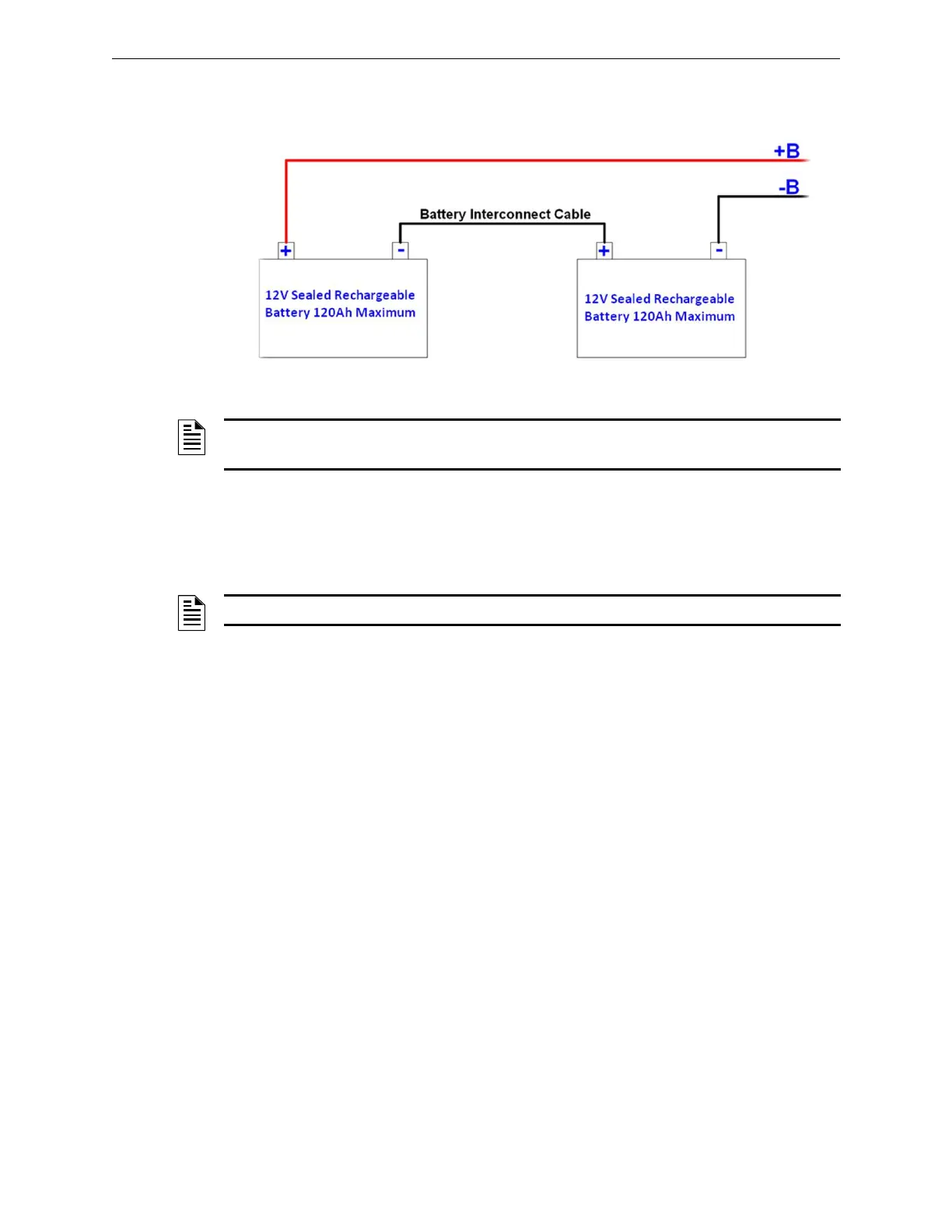
calculate the proper capacity of the batteries to be used. Open S1 disconnect switch, connect the red
cable marked with +B to the positive pole of the batteries and the black cable marked with –B to the
negative pole of the batteries; then close S1 disconnect switch.
3.11.1 Replacement of Battery Fuses
To replace battery protection fuses, open the disconnect switch S1, remove the blown fuses and
replace them with two equivalent or identical ones; then close the disconnect switch S1 again.
3.12 Instructions for the Connection of Field Devices
All the interconnecting cables of field devices must be duly identified and terminated with suitable
end ferrules (the end of a stranded conductor must not be consolidated with a soft soldering in the
places where the conductor is subject to contact pressure). During wiring, make sure to keep the
cables of field devices (Inputs/Outputs) and the power cables separate.
3.12.1 Balanced Input Cables
For this type of signal we recommend using shielded twisted cables CEI EN 50200 2 x 1 mm
2
.
3.12.2 4-20 mA Analog Input Cables
For this type of signal we recommend using shielded twisted cables CEI EN 50200 3 x 1.5 mm
2
. In
this case, please take utmost care when selecting the conductors to avoid that the voltage drop along
the cable may prevent the connected devices from operating.
Figure 3.8 Internal Batteries
NOTES:The two batteries shall have the same Ah capacity.
Do not connect the batteries in parallel to obtain higher capacity.
NOTE: Batteries can power the control panel only after the primary mains voltage is supplied.
 Loading...


