H-S81-HS Installation & Operation Manual — P/N LS10114-000HI-E:A 2/24/2015 35
Power Supply Set Parts of the H-S81-HS System
Open collector replications
RS 232
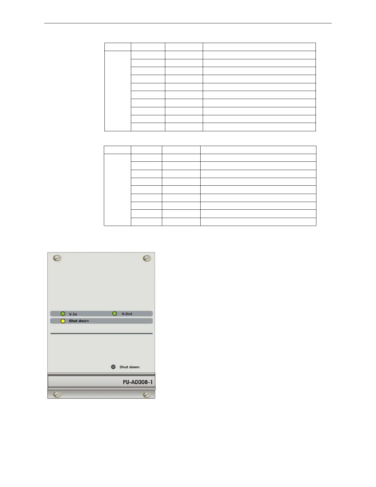
2.1.6 PU-A0008-1 Power Supply Module
Description
It is a switching power supply unit with universal input able to pro-
vide a maximum current of 20A at 25VDC. It is placed in a 19 inch
rack slot and used in combination with the PU-A0009-1 battery char-
ger in compliance with EN54-4 standard. The power supply unit fea-
tures a circuit for load distribution which allows the parallel
connection of multiple power supply units, up to a maximum of four
units. Module hot swapping is allowed (Hot Plug). On the front panel
there are: two green LEDs signaling the proper presence of input and
output voltage; a yellow LED that lights up in case of failure; and a
button for shutting the module down before hot-swapping.
Tag Terminal Name Function
8
M1 PSU1-Fault Primary power supply failure
M2 PSU2-Fault Secondary power supply failure
M3 Fault Internal failure
M4 Battery status Battery status (charge/supply)
M5 Charge Status Battery charge status (full charge/trickle charge)
M6 Rip.1 Programmable output
M7 Rip.2 Programmable output
M8 GND External temperature probe display
M9 +S External temperature probe positive
M10 -S External temperature probe negative
Tag Pin Name Function
9
1 N.C. Not used
2 Txd RS232 data transmission
3 Rxd RS232 data reception
4 N.C. Not used
5 GND RS232 common
6 N.C. Not used
7 N.C. Not used
8 N.C. Not used
9 N.C. Not used
 Loading...


