208
Alarm Setpoints Display
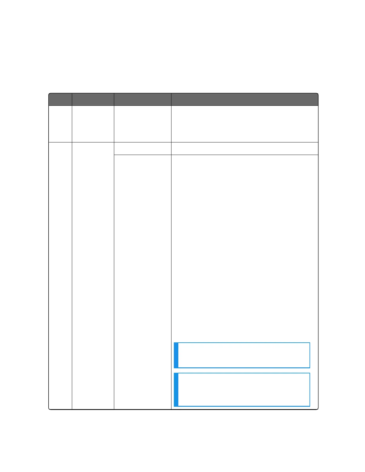
Table 5-17: Procedure for Displaying Alarm Setpoints
Step Operation Press Result
1 Select
Alarms
Set-up
Group
Setup key or
Increment key or
Decrement key
Until you see Alarms set up group
2 Select the
Alarm
Setpoint
Values
Function key Enter in the first function prompt A1S1 Type.
Increment key or
Decrement key
Until you see the required Alarm setpoint.
A1S1 Value = Alarm 1, Setpoint 1 Value
A1S2 Value = Alarm 1, Setpoint 2 Value
A2S1 Value = Alarm 2, Setpoint 1 Value
A2S2 Value = Alarm 2, Setpoint 2 Value
To successively display the alarm setpoints
and their values. Their order of appearance is
shown below.
Lower Display = (the alarm setpoint value)
Range values are within the range of the
selected parameters except:
Deviation value = PV Span
Events (Event On/Event Off) value = Event
Segment Number
PV Rate of Change = The amount of PV
change in one minute in engineering units.
Loop Break Alarms (Loop Break)= The timer
value may be changed only for controllers
configured for ON/OFF control.
NOTE: With Three position step control,
alarms set for “output” will not function.
NOTE: Manual, Remote Setpoint, and
Failsafe selections do not have setpoint
values.
Chapter 5 - Monitoring and Operating the Controller

 Loading...


