242
Calibrator Connections
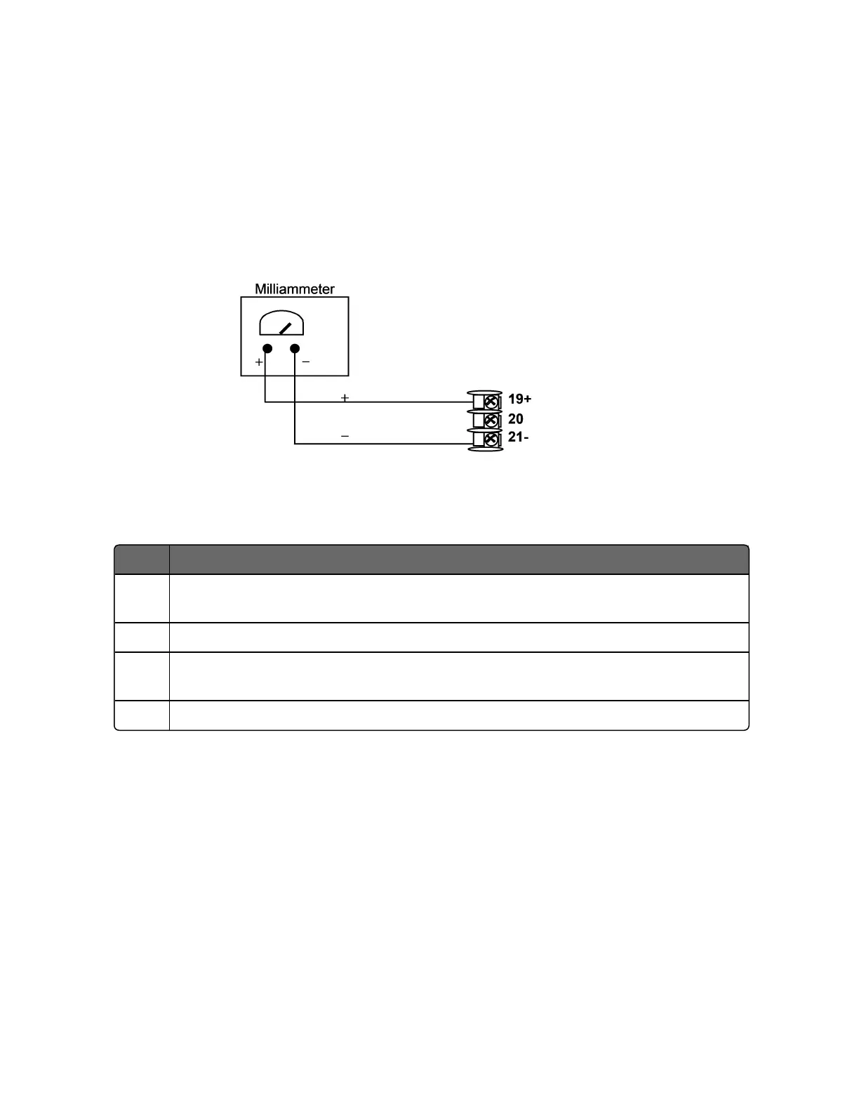
Refer to figure below and wire the controller according to the
procedure given in the table.
Figure 7-1: Wiring Connections for Calibrating Current Proportional
Output
Table 7-1: Set Up Wiring Procedure for Current Output
Step Action
1 Apply power and allow the controller to warm up 30 minutes before you
calibrate.
2 Set Lockout in the Security set up group to None.
3 Tag and disconnect the field wiring, at the rear of the controller, from terminals
21 (–) and 19 (+). Seefigure below.
4 Connect a milliammeter across these terminals.
Procedure
The procedure for calibrating the Current Output is listed in table
below.
Make sure Lockout in the Security set up group is set to None. See
Security Set Up Group for more information.
Chapter 7 - Output Calibration

 Loading...


