12. When the analyzer displays 'DONE' IF FINISHED WITH CAL, press
::..
&$&
L-
‘:~~~~~~~~~
13. Press
CSa”e,Reca,,,
~~~~~~~,:,
*
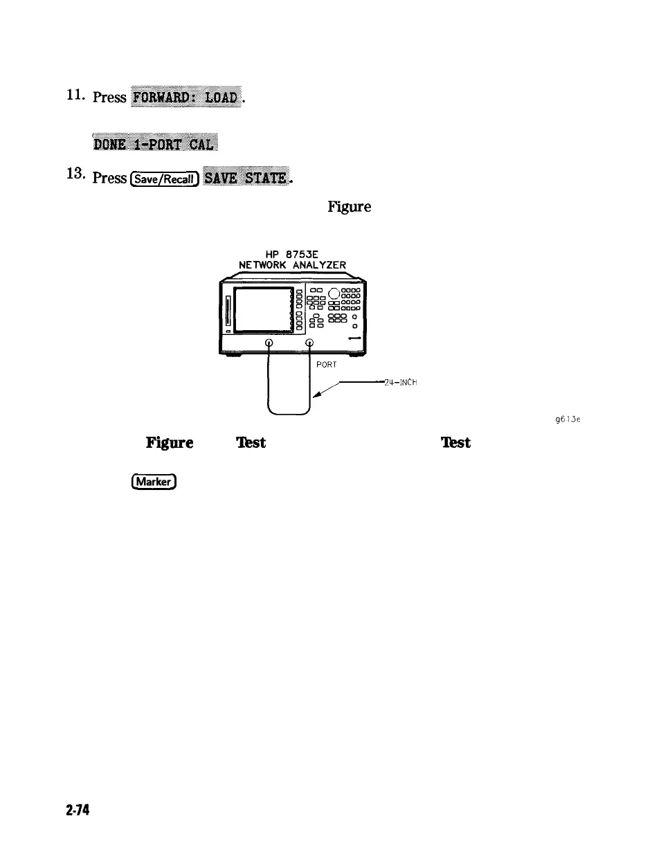
14. Connect the equipment as shown in Figure 2-34.
PORT 1 PORT 2
U-.
-
Z-INCH
CABLE
g613e
Fiure
2-34.
‘Jkst
Port 2 Input Impedance
‘Jkst
Setup
15. Press
e
to turn the analyzer’s marker 1 on. Use the front panel knob
to locate the maximum value of the data trace for each of the frequency
ranges listed in the “Performance Test Record.”
16. Write these maximum values on the “Performance Test Record.”
17. Connect the equipment as shown in Figure 2-35.
2-74
System Verification and
Performance Tests