5. To make sure that you have connected the test points properly, adjust the
CAV ADJ potentiometer while observing the analyzer display. You should
notice a change in voltage.
6. Observe the phase locked loop error voltage:
w
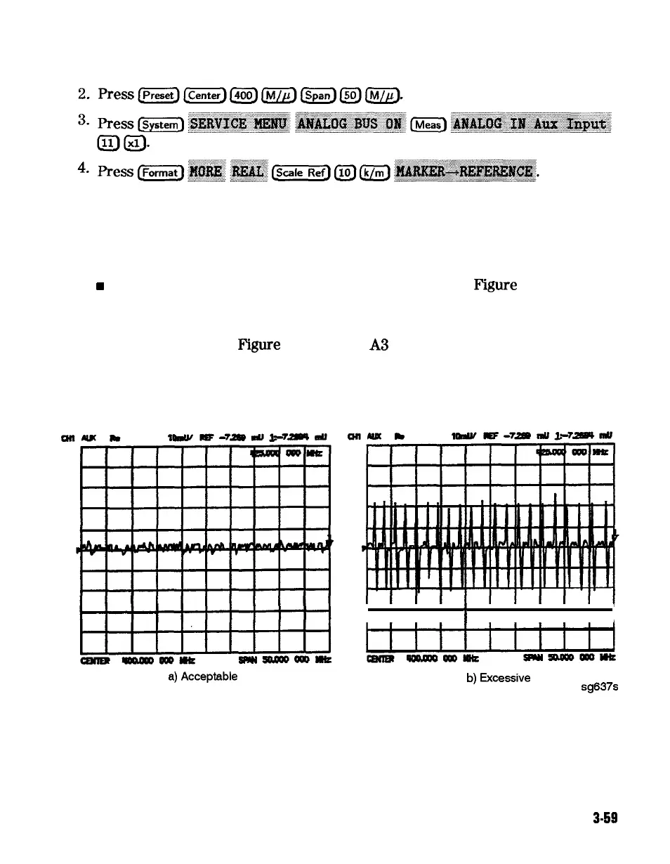
If “spikes” are not visible on the analyzer display (see
Figure
3-25): no
adjustment is necessary.
n
If “spikes” are excessive (see Figure 3-25): adjust the CAV ADJ
potentiometer (see
Pigure
3-24) on the
A3
source bias assembly to eliminate
the spikes.
n If the “spikes” persist, refer to Chapter 7, “Source Troubleshooting.”
I i
i
i
i
i
i
i ii 1
a)
Acceptable
b)
Excessive
sg637s
Figure 3-25. Display of Acceptable versus Excessive Spikes
Adjustments and Correction Constants
3-59