Check the A and B Inputs
Good inputs produce traces similar to Figure 8-2 in terms of flatness. To examine
both input traces, do the following:
1.
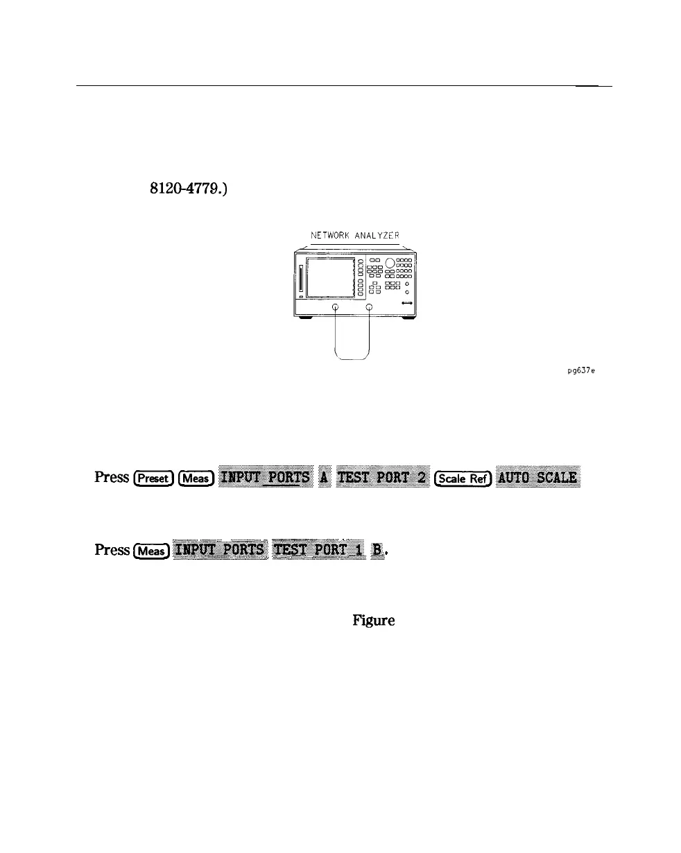
Connect the equipment as shown in Figure 8-1. (The through cable is HP part
number
8120-4779.)
NETWORK
ANALYZER
Figure S-l. Equipment Setup
2.
3.
Check the flatness of the input A trace by comparing it with the trace in
Figure
8-2.
Check the flatness of the input B trace by comparing it with the trace in
Figure 8-2.
:.:...............................
__
....
...................
..~.~...~.~
......
.
_
................................
...
)
p
.:.:.:.:.:
....
/
....
fie3
1Meao)
..................
::..:...:.:.:.:
..............................................
............
_.
..........
..-.
_.
......................
_.
...
iiii.
.....................
2..
~~~~~~~~.,
;@)
:.z.x.:.:
.-
,.
:.:.:.z.:.&
...
... ...........
ii
..............................
.._
........
:.:.::.,_L :cz.:.m
q
If neither of the input traces resembles Figure 8-2, continue with
“Troubleshooting When All Inputs Look Bad”.
q
If at least one input trace resembles
Figure
8-2, continue with
“Troubleshooting When One or More Inputs Look Good”.
84 Receiver Troubleshooting