R
CHANNEL IN
*
r
P
ADAPTER
APC-3.5
(m)
TO
WC-7
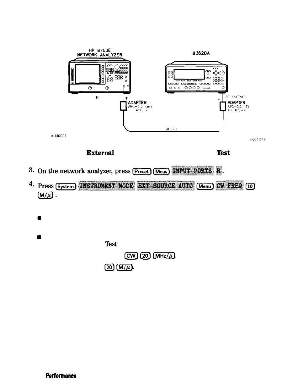
HP
83620A
SYNTHESIZER
*
DRECT CONNECTION
\
CABLE APCG7 24 INCH
J
sgE121e
Figure 2-9.
Exterml
Source Mode Frequency Range
lkst
Setup
5.
Check to see if the analyzer is phase locking to the external CW signal:
H
If the analyzer displays any phase lock error messages, write “unlock” in
the “Performance Test Record” for the set CW signal.
w
If the analyzer does not display any phase lock error messages, write “lock”
in the “Performance
Test
Record” for the set CW signal.
6.
On the external source, press
m
L20)
[j].
7.
On the analyzer, press
I2oJ
m.
8. Repeat step 5 through 7 for the other external source CW frequencies listed
in the “Performance Test Record.”
2-22 System Verification and
Periormance
Tests