The switches connected through the interfaces on the VSTSA belong to a switching domain and
are considered as a device. Users can manage all the switches in a stack on the master switch.
Application
The VSTSA can be installed on the SRU of the S9312 or S9306. When the stack is to be
configured, both the SRU in the same chassis must be installed with the VSTSA.
NOTE
The FSUA and the VSTSA are installed in the subcard slots of the SRUs. The FSUA and the VSTSA
cannot be installed in the same chassis.
The VSTSA can be installed on the LE02 SRUA VER.A.
5.5.3 Panel
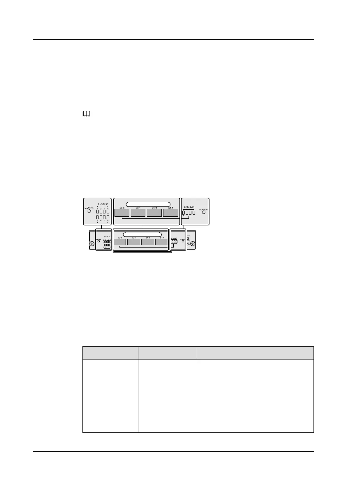
Figure 5-14 shows the appearance of the VSTSA panel.
Figure 5-14 Appearance of the VSTSA panel
1. Master state indicator
2. Stack ID indicator 3. ACT/LINK indicator 4. RUN/ALM indicator
Buttons and Indicators on the Panel
Table 5-24 describes the buttons and indicators on the VSTSA panel.
Table 5-24 Description of the buttons and indicators on the VSTSA panel
Indicator/Button
Color Description
MASTER Green If the indicator is on, it indicates that the SRU
where the VSTSA is installed is the master in
the stack.
If the indicator is off, the SRU where the
VSTSA is installed may be:
l The standby SRU on the master switch
l The active SRU on the slave switch
l The standby SRU on the slave switch
Quidway S9300 Terabit Routing Switch
Hardware Description 5 Boards
Issue 01 (2010-12-15) Huawei Proprietary and Confidential
Copyright © Huawei Technologies Co., Ltd.
5-27

 Loading...


