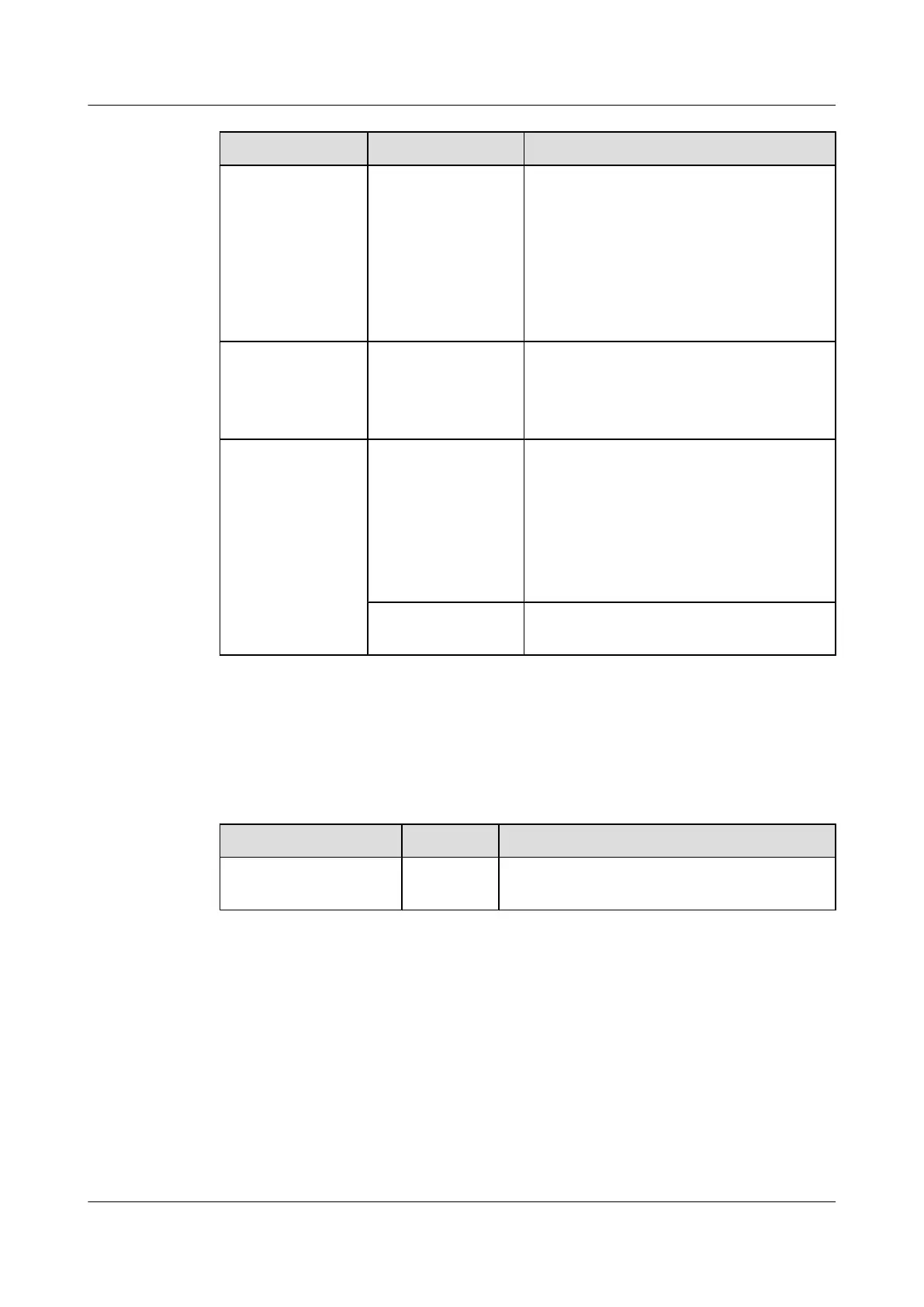
Indicator/Button Color Description
STACK ID Green This indicator shows the ID of the stack.
Currently, a stack can contain up to two
switches; therefore, only the indicators of
stack 1 and stack 2 may be on.
When both the two SRUs are installed with the
VSTSA, the stack ID indicators must be the
same. That is, the stack 1 indicators or stack 2
indicators are on.
ACT/LINK
Green If the indicator is on, it indicates the state of
link is UP.
If the indicator is on, it indicates that the state
of link is DOWN.
RUN/ALM Green If the indicator is on, it indicates that the board
is powered on but the software is not running.
If the indicator blinks once every 2s (0.5 Hz),
it indicates that the system is in normal state.
If the indicator blinks once every 0.25s (4 Hz),
it indicates that the system is being powered
on or being restarted.
Red
If the indicator is on, it indicates that the board
is faulty.
5.5.4 Interfaces
Table 5-25 describes the types and functions of the interfaces on the VSTSA.
Table 5-25 Types and functions of the interfaces on the VSTSA
Name
Quantity Description
16G BASE-T electrical
interface
4 The VSTSA provides four 16-Gbit/s electrical
interfaces to transmit and receive services.
The VSTSA provides four interfaces: S0-0, S0-1, S1-0, and S1-1. The S9300 currently supports
the stack of up to two switches. When S9300A and S9300B are connected through VSTSAs,
the interfaces are connected as Figure 5-15 shows.
5 Boards
Quidway S9300 Terabit Routing Switch
Hardware Description
5-28 Huawei Proprietary and Confidential
Copyright © Huawei Technologies Co., Ltd.
Issue 01 (2010-12-15)

 Loading...


