– Each AC power supply is configured in PWR2 and PWR4, and the filler panels are
installed in PWR1 and PWR3.
– Each AC power supply is configured in PWR1 and PWR4, and the filler panels are
installed in PWR2 and PWR3.
– 2+2 configuration, 110 V AC power supplies (800 W)
One 110 V AC power supplies provide power of 400 W. To meet the power requirement
of the S9306, the backup mode must be adopted for 110 V AC power supplies. The AC
power supplies are installed in the PWR1 to PWR4 slots.
S9303
The power supplies are located in the PWR1 to PWR2 slots of the S9303. The DC power supplies
and AC power supplies are supported. PWR1 is in area A, and PWR2 is in area B. Area A and
area B work in backup mode, as shown in Figure 3-3.
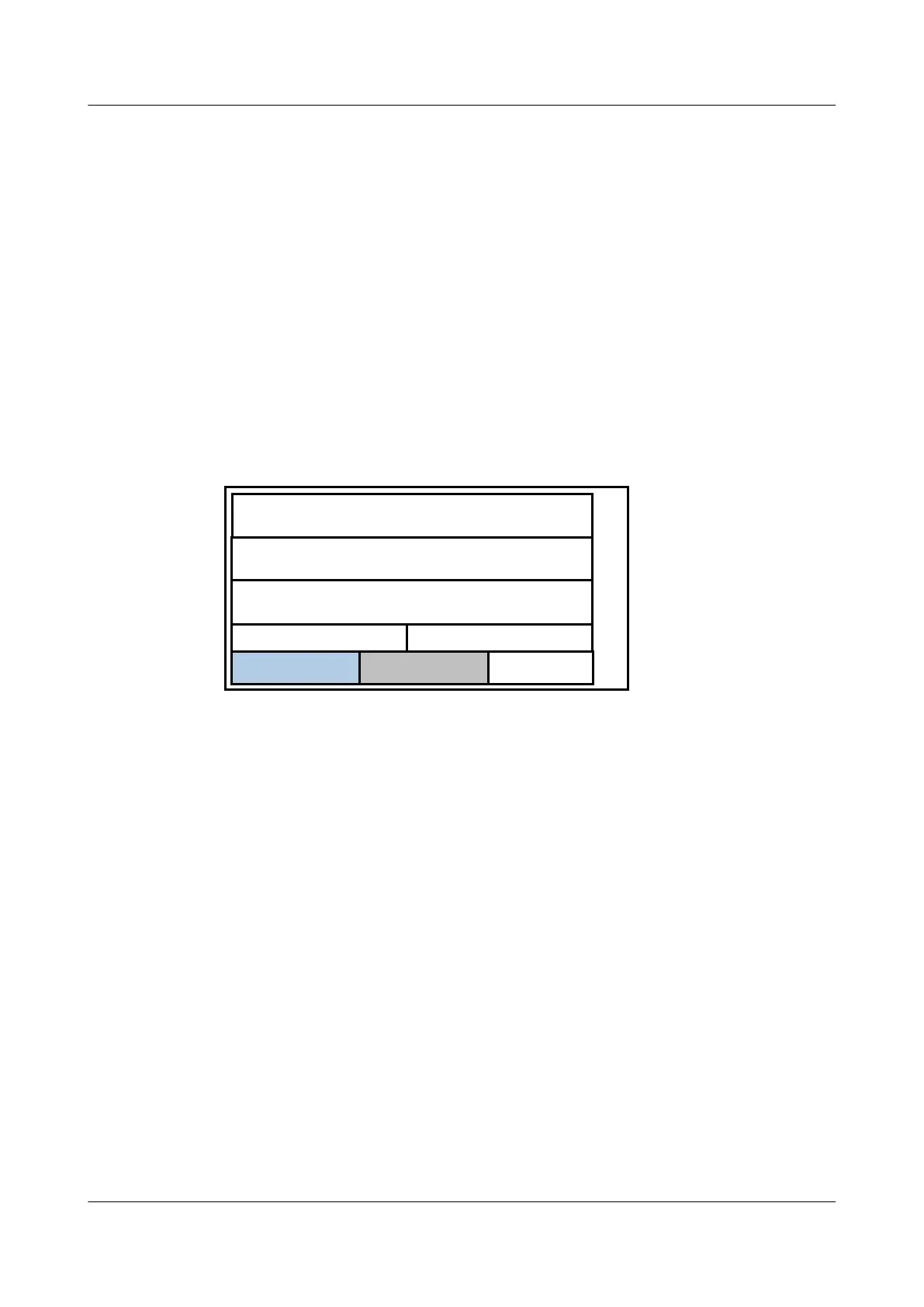
Figure 3-3 Configuration of the S9303 power supplies
电源模块
LPU
MCU MCU
LPU
LPU
PoE
PW R1 PW R2
Master PWR Slave PWR
The maximum power consumption of the S9303 is 350 W. You can use DC power supplies or
AC power supplies on the S9303.
l DC power supplies, 1+1 configuration
Each power supply is configured in active area A and standby area B. The two power
supplies work in backup mode, as shown in Figure 3-3.
l Configuration of the S9303 AC power supplies
– 1+1 configuration, 220 V AC power supplies (800 W)
The maximum power consumption is 800 W. Each AC power supply is configured in
active area A and standby area B, as shown in Figure 3-3.
– 1+1 configuration, 110 V AC power supplies (400 W)
Two 110 V AC power supplies provide power of 400 W. The total power consumption
of the S9303 is less than 400 W; therefore, the S9303 can use two 110 V AC power
supplies in backup mode, as shown in Figure 3-3.
3.1.2 Power Supply Principle
Figure 3-4 shows the principle of the DC power supplies on the S9300. Figure 3-5 shows the
principle of the AC power supplies.
3 Power Supply
Quidway S9300 Terabit Routing Switch
Hardware Description
3-6 Huawei Proprietary and Confidential
Copyright © Huawei Technologies Co., Ltd.
Issue 01 (2010-12-15)

 Loading...


