Table 2-2 Components of the S9306
Component Description Reference
SRU The SRUs are installed in slot 7 and slot 8 and
work in 1:1 backup mode with the data switching
units working in either 1+1 load balancing mode
or 1:1 backup mode. The interval between slot 7
and slot 8 is 1.4 inches.
See 5.2 SRU - Main
Control Unit.
LPU The LPUs are installed in slots 1-6. The interval
between each two slots is 1.4 inches.
See 5 Boards.
CMU The CMUs are installed in slots CMU1 and
CMU2, working in 1:1 backup mode.
See 5.6 CMU -
Centralized
Monitoring Unit.
Fan module The fan modules are installed at the rear of the
equipment. The equipment must be equipped with
two fan modules.
See 4.2 Fan
Module.
Power supply The power supplies are installed in slots PWR1 to
PWR4. The S9306 can use DC or AC power
supplies.
See 3 Power
Supply.
Cabling rack The cable distribution posts are located on the
right side of the board cage of the S9306.
-
Cable The cables of the S9306 include internal cables
(such as power cables and signal cables), optical
fibers, and external cables.
See 6 Cables.
2.2.3 S9303
The S9303 is 4 U (1 U = 44.45 mm) high, with dimensions of 442 mm x 476 mm x 175 mm
(width x depth x height). Figure 2-7 and Figure 2-8 shows the appearance and components of
the S9306. Figure 2-9 shows the layout of slots on the S9303.
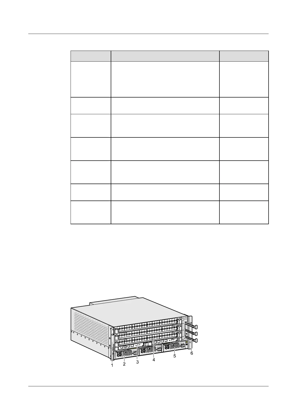
Figure 2-7 Appearance and components of the S9303 (1)
1. Rack-mounting ear
2. Power supply 3. MCU
2 Overview of the S9300
Quidway S9300 Terabit Routing Switch
Hardware Description
2-8 Huawei Proprietary and Confidential
Copyright © Huawei Technologies Co., Ltd.
Issue 01 (2010-12-15)

 Loading...


