4. LPU 5. PoE Power Module 6. Cabling rack
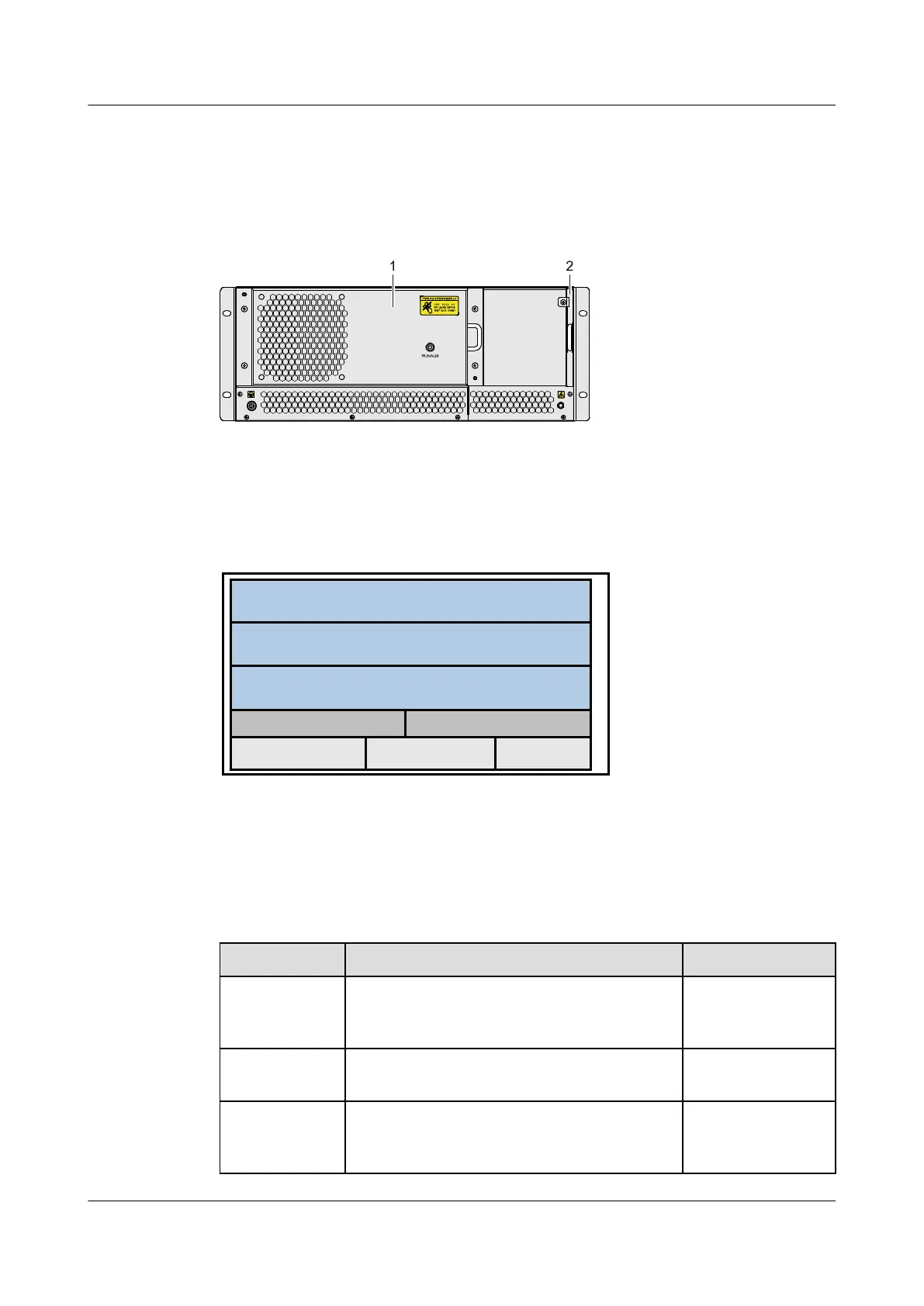
Figure 2-8 Appearance and components of the S9303 (2)
1. Fan 2. Air filter
Figure 2-9 Layout of slots on the S9303
电源模块
SLOT1-LPU
SLOT4-MCU SLOT5-MCU
PWR1 PWR2
SLOT2-LPU
SLOT3-LPU
PoE
The S9303 uses an integrated chassis of which the main components are described in Table
2-3.
Table 2-3 Components of the S9303
Component
Description Reference
MCU The MCUs are installed in slot 4 and slot 5 and
work in 1:1 backup mode. The interval between
slot 4 and slot 5 is 0.8 inches.
See 5.3 MCUA -
Main Control Unit.
LPU The LPUs are installed in slots 1-3. The interval
between each two slots is 1.4 inches.
See 5 Boards.
Fan module The fan modules are installed at the rear of the
equipment. The equipment must be equipped with
one fan module.
See 4.2 Fan
Module.
Quidway S9300 Terabit Routing Switch
Hardware Description 2 Overview of the S9300
Issue 01 (2010-12-15) Huawei Proprietary and Confidential
Copyright © Huawei Technologies Co., Ltd.
2-9

 Loading...


