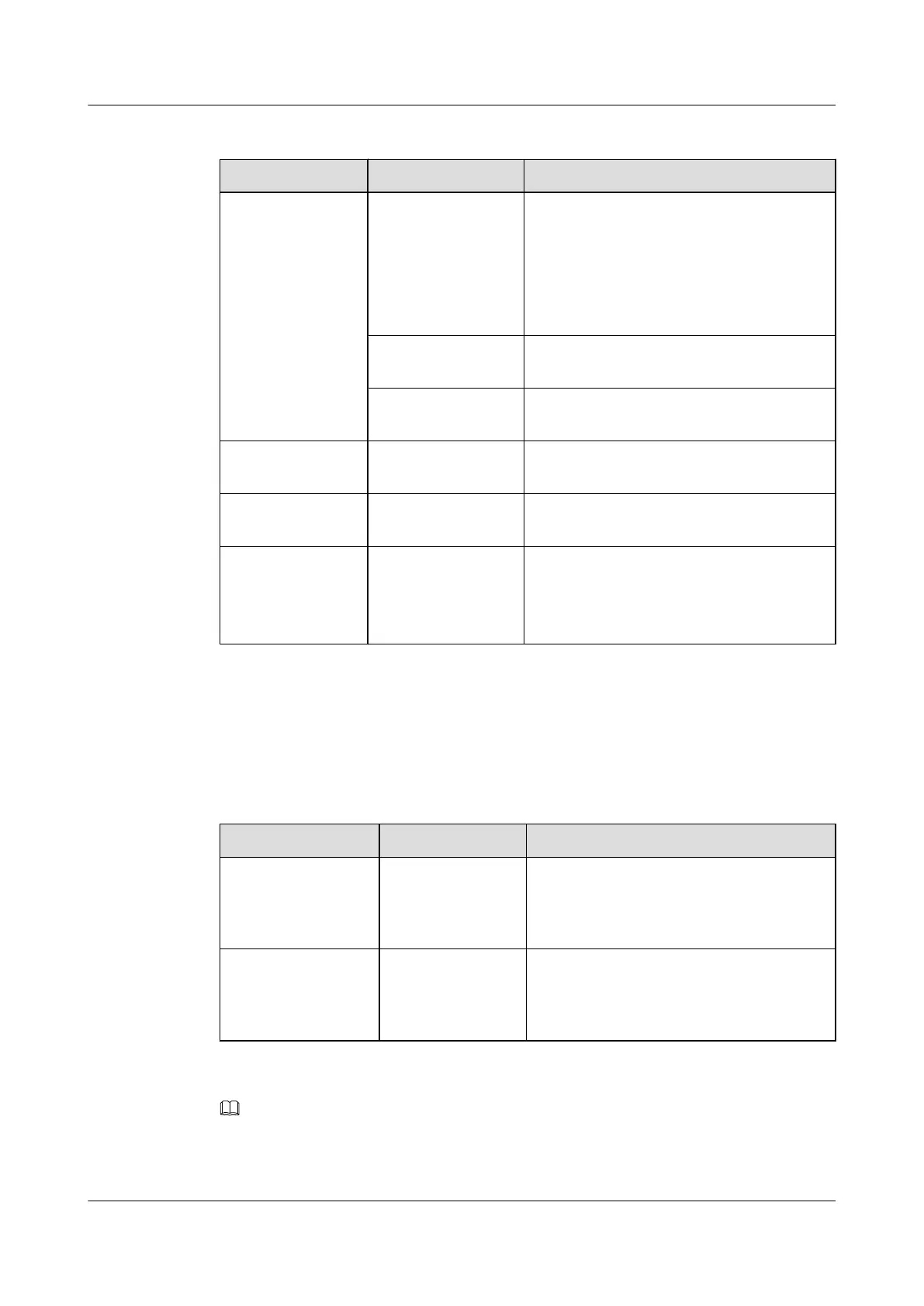
Table 5-78 Description of buttons and indicators on the G24CEAS panel
Indicator/Button Color Description
RUN/ALM Green If the indicator is on, it indicates that the board
is powered on but the software is not running.
If the indicator blinks once every 2s (0.5 Hz),
it indicates that the system is in normal state.
If the indicator blinks once every 0.25s (4 Hz),
it indicates that the system is being started.
Red
If the indicator is on, it indicates that the board
is faulty.
Orange If the indicator is on, it indicates that the board
is installed in the slot and is powered on.
ACT Amber If the indicator blinks, it indicates that data is
being transmitted.
LINK Green-yellow If the indicator is on, it indicates that the link
is connected.
LINK/ACT Green If the indicator is on, it indicates that the link
is connected.
If the indicator blinks, it indicates that data is
being transmitted.
5.15.4 Interfaces
Table 5-79 describes the types and functions of the interfaces on the G24CEAS.
Table 5-79 Types and functions of the interfaces on the G24CEAS
Name
Quantity Description
10M/100M/1000M
BASE-T electrical
interface
8 The G24CEAS provides 8 Ethernet electrical
interfaces (10M/100M/1000M auto sensing)
to transmit and receive 1000 Mbit/s Ethernet
services.
100M/1000M BASE-
X optical interface
24 The G24CEAS provides 24 Ethernet optical
interfaces (100M/1000M auto sensing) to
transmit and receive 1000 Mbit/s Ethernet
services.
NOTE
A Combo interface works as either an optical interface or an electrical interface. You can run the combo-
port { copper | fiber } command to set the mode of the Combo interface.
5 Boards
Quidway S9300 Terabit Routing Switch
Hardware Description
5-66 Huawei Proprietary and Confidential
Copyright © Huawei Technologies Co., Ltd.
Issue 01 (2010-12-15)

 Loading...


