80C187
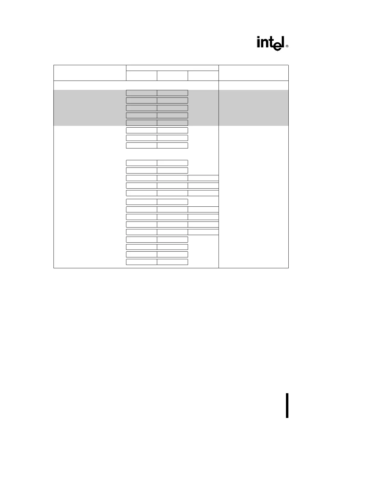
80C187 Extensions to the 80C186 Instruction Set (Continued)
Encoding
Instruction
Byte Byte Optional
Clock Count Range
0 1 Bytes 2–3
TRANSCENDENTAL
FCOS
e
Cosine of ST(0) ESC 001 1111 1111 125–774
j
FPTAN
k
e
Partial tangent of ST(0) ESC 001 1111 0010 193–499
j
FPATAN
e
Partial arctangent ESC 001 1111 0011 316–489
FSIN
e
Sine of ST(0) ESC 001 1111 1110 124– 773
j
FSINCOS
e
Sine and cosine of ST(0) ESC 001 1111 1011 196–811
j
F2XM1
l
e
2
ST(0)
b
1 ESC 001 1111 0000 213–478
FYL2X
m
e
ST(1) * log
2
(ST(0)) ESC 001 1111 0001 122– 540
FYL2XP1
n
e
ST(1) * log
2
(ST(0)
a
1.0) ESC 001 1111 1001 259–549
PROCESSOR CONTROL
FINIT
e
Initialize NPX ESC 011 1110 0011 35
FSTSW AX
e
Store status word ESC 111 1110 0000 17
FLDCW
e
Load control word ESC 001 MOD 101 R/M DISP 23
FSTCW
e
Store control word ESC 001 MOD 111 R/M DISP 21
FSTSW
e
Store status word ESC 101 MOD 111 R/M DISP 21
FCLEX
e
Clear exceptions ESC 011 1110 0010 13
FSTENV
e
Store environment ESC 001 MOD 110 R/M DISP 146
FLDENV
e
Load environment ESC 001 MOD 100 R/M DISP 113
FSAVE
e
Save state ESC 101 MOD 110 R/M DISP 550
FRSTOR
e
Restore state ESC 101 MOD 100 R/M DISP 482
FINCSTP
e
Increment stack pointer ESC 001 1111 0111 23
FDECSTP
e
Decrement stack pointer ESC 001 1111 0110 24
FFREE
e
Free ST(i) ESC 101 1100 0 ST(i) 20
FNOP
e
No operations ESC 001 1101 0000 14
Shaded areas indicate instructions not available in 8087.
NOTES:
j. These timings hold for operands in the range
l
x
l
k
q/4. For operands not in this range, up to 78 clocks may be needed to
reduce the operand.
k. 0
s
l
ST(0)
l
k
2
63
.
l.
b
1.0
s
ST(0)
s
1.0.
m. 0
s
ST(0)
k
%
,
b%
k
ST(1)
k
a %
.
n. 0
s
l
ST(0)
l
k
(2
b
S
(2))/2,
b%
k
ST(1)
k
a %
.
DATA SHEET REVISION REVIEW
The following list represents the key differences between the -002 and the -001 version of the 80C187 data
sheet. Please review this summary carefully.
1. Figure 10, titled ‘‘System Configuration for 8087ÐCompatible Exception Trapping’’, was replaced with a
revised schematic. The previous configuration was faulty. Updated timing diagrams on Data Transfer Tim-
ing, Error Output, and RESET/BUSY.
30