8254
231164–7
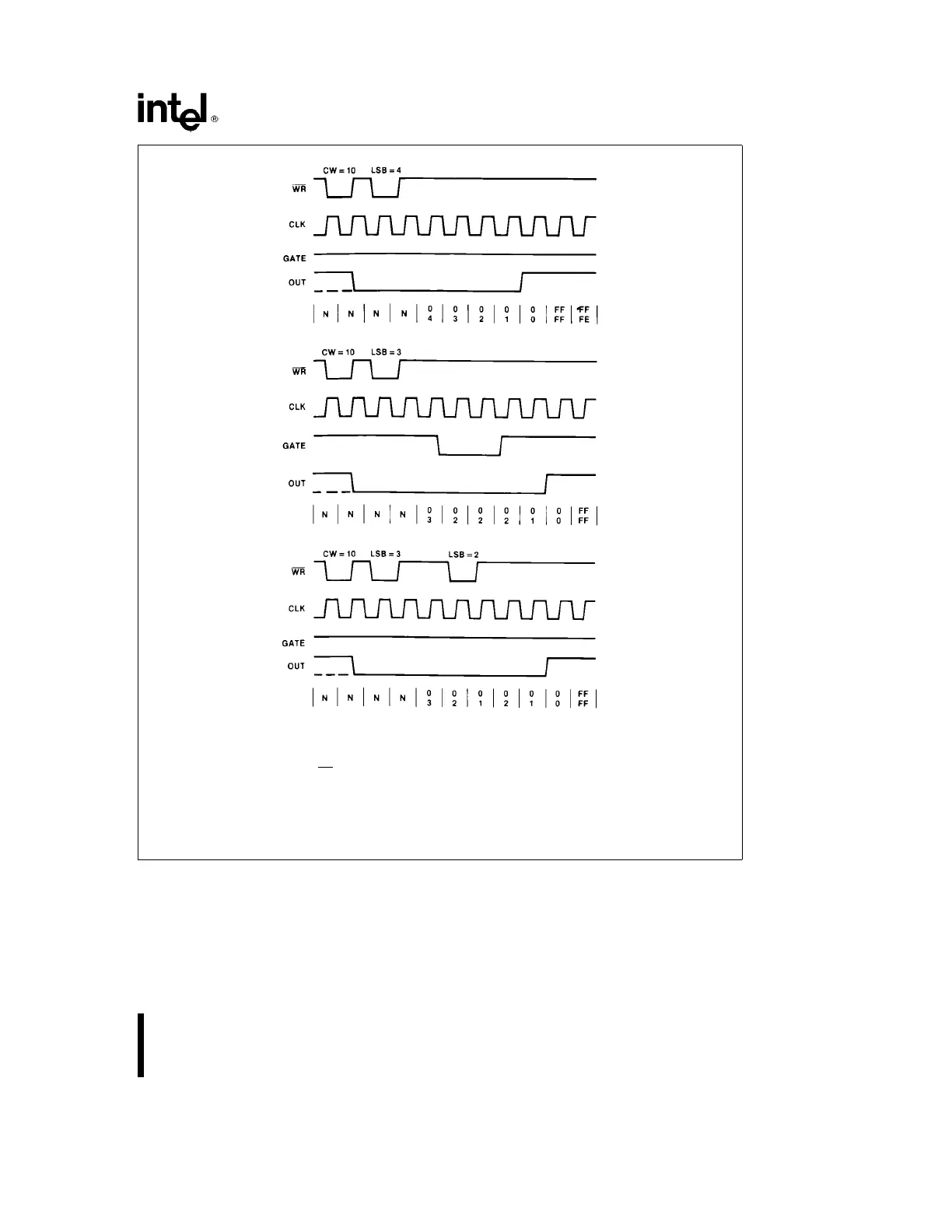
NOTE:
The following conventions apply to all mode timing diagrams:
1. Counters are programmed for binary (not BCD) counting and for reading/writing least significant byte (LSB) only.
2. The counter is always selected (CS
always low).
3. CW stands for ‘‘Control Word’’; CW
e
10 means a control word of 10 HEX is written to the counter.
4. LSB stands for ‘‘Least Significant Byte’’ of count.
5. Numbers below diagrams are count values. The lower number is the least significant byte. The upper number is the
most significant byte. Since the counter is programmed to read/write LSB only, the most significant byte cannot be read.
N stands for an undefined count.
Vertical lines show transitions between count values.
Figure 15. Mode 0
11