82C54
If an initial count is written while GATE
e
0, it will
still be loaded on the next CLK pulse. When GATE
goes high, OUT will go high N CLK pulses later; no
CLK pulse is needed to load the Counter as this has
already been done.
231244–8
NOTE:
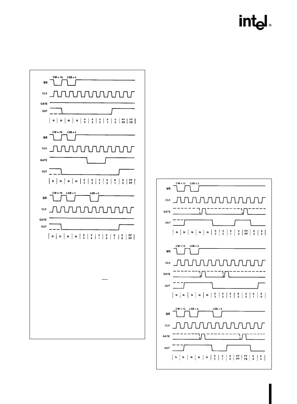
The Following Conventions Apply To All Mode Timing
Diagrams:
1. Counters are programmed for binary (not BCD)
counting and for Reading/Writing least significant byte
(LSB) only.
2. The counter is always selected (CS
always low).
3. CW stands for ‘‘Control Word’’; CW
e
10 means a
control word of 10, hex is written to the counter.
4. LSB stands for ‘‘Least Significant Byte’’ of count.
5. Numbers below diagrams are count values.
The lower number is the least significant byte.
The upper number is the most significant byte. Since
the counter is programmed to Read/Write LSB only,
the most significant byte cannot be read.
N stands for an undefined count.
Vertical lines show transitions between count values.
Figure 15. Mode 0
MODE 1: HARDWARE RETRIGGERABLE
ONE-SHOT
OUT will be initially high. OUT will go low on the CLK
pulse following a trigger to begin the one-shot pulse,
and will remain low until the Counter reaches zero.
OUT will then go high and remain high until the CLK
pulse after the next trigger.
After writing the Control Word and initial count, the
Counter is armed. A trigger results in loading the
Counter and setting OUT low on the next CLK pulse,
thus starting the one-shot pulse. An initial count of N
will result in a one-shot pulse N CLK cycles in dura-
tion. The one-shot is retriggerable, hence OUT will
remain low for N CLK pulses after any trigger. The
one-shot pulse can be repeated without rewriting the
same count into the counter. GATE has no effect on
OUT.
If a new count is written to the Counter during a one-
shot pulse, the current one-shot is not affected un-
less the Counter is retriggered. In that case, the
Counter is loaded with the new count and the one-
shot pulse continues until the new count expires.
231244–9
Figure 16. Mode 1
10