Functional Description (Continued)
5.3 Multiple A/D Converters in a Z-80 Interrupt Driven
Mode (Continued)
The following notes apply:
•
It is assumed that the CPU automatically performs a RST
7 instruction when a valid interrupt is acknowledged
(CPU is in interrupt mode 1). Hence, the subroutine start-
ing address of X0038.
•
The address bus from the Z-80 and the data bus to the
Z-80 are assumed to be inverted by bus drivers.
•
A/D data and identifying words will be stored in sequen-
tial memory locations starting at the arbitrarily chosen ad-
dress X 3E00.
•
The stack pointer must be dimensioned in the main pro-
gram as the RST 7 instruction automatically pushes the
PC onto the stack and the subroutine uses an additional
6 stack addresses.
•
The peripherals of concern are mapped into I/O space
with the following port assignments:
DS005671-A5
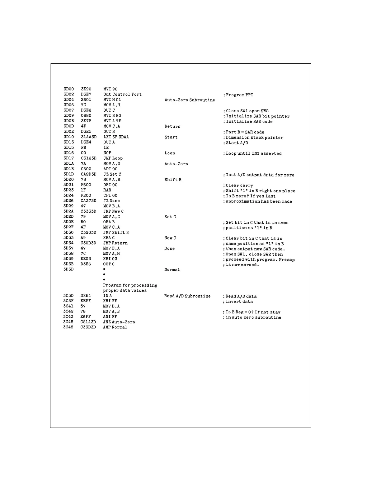
Note 29: All numerical values are hexadecimal representations.
FIGURE 21. Software for Auto-Zeroed Differential A/D
ADC0801/ADC0802/ADC0803/ADC0804/ADC0805
www.national.com37