3/24/97 4-1 CPU Organization
4 CPU Organization
This chapter describes the Central Processing Unit (CPU) of the XA Core. The CPU contains all
status and control logic for the XA architecture. The XA reset sequence and the system oscillator
interface with the CPU, and power control is handled here. The CPU performs interrupt and
exception handling. The XA CPU is equipped with special functions to support debugging.
4.1 Introduction
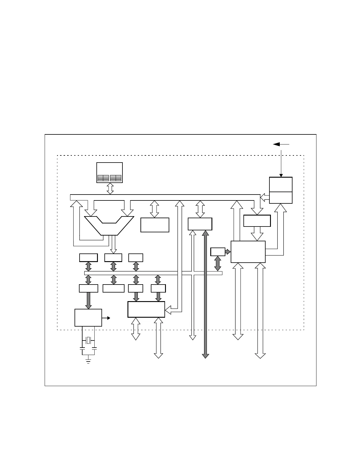
Figure 4.1 is a block diagram of the XA Core.
Figure 4.1 The XA Core
Here is an overview of core elements: The XA Core oscillator provides a basic system clock.
Timing and control logic are initialized by an external reset signal; once initialized, this logic
SFR bus
interface
Exception
Controller
Program
Counter
On-chip
Peripherals
On-chip
EPROM/
ROM
PSWL
PSWH
SCR
SSELPCON ES DS
Data/Address/Control Bus
RESET
Oscillator
16-bit
CS
External
Program
Memory
External
Data
Memory
On-chip
RAM
Program
Memory
Interface
ALU
16-bit
Data Memory
Interface
External
SFR
Devices
Register
File
Execution
Unit
IREG
CPU
Clock
SFR bus
8 or 16 bits