XA User Guide 4-8 3/24/97
4.4.3 Internal Reset Sequence
The XA internal reset sequence occurs after power-up or any time a sufficiently long reset pulse
is applied to the RST input while the XA is operating. This sequence requires a minimum of a 10
microseconds (or 10 clocks, whichever is greater) to complete, and
RST must remain low for at
least this long.
The internal reset sequence does the following:
• Writes a 00 to most core and many peripheral SFRs. Other values are written to some periph-
eral SFRs. Consult the data sheet of a specific device for details.
• Sets CS, DS, and ES to 0.
• Sets SSEL = 0, i.e., sets all accesses through DS.
• Sets all registers in the Register File to 0.
• Sets the user and the system stack pointers (USP and SSP) to 0100h.
• Clears SCR bit PZ, i.e., 24-bit memory addresses will be used by default.
• Clears SCR bit CM, i.e., starts execution in XA Native Mode.
• Clears IE bit EA, disabling all maskable interrupts.
Note that the internal reset sequence does not initialize internal or external RAM. Note also that
the contents of PSW at this point is not important, as it will immediately be replaced as
described further below.
The effect of the internal reset sequence on components outside the XA core depends on the
peripheral complement and configuration of the specific XA derivative. In general, the internal
reset sequence has the following effects:
• Sets all port pins to inputs (quasi-bidirectional output configuration with port value = FF hex)
• Clears most SFRs to 0
• Initializes most other SFRs to appropriate non-zero values
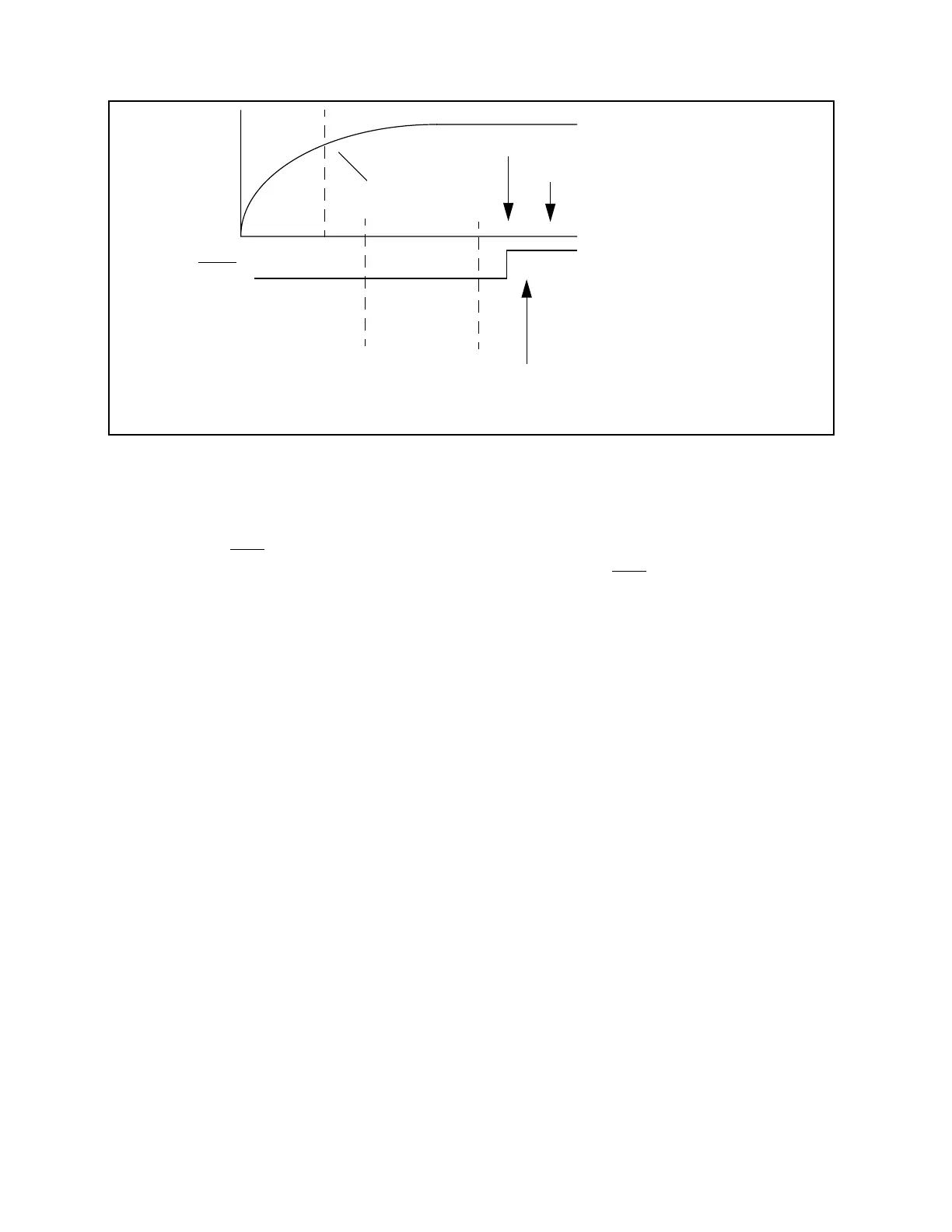
Figure 4.6 XA power-up sequence
Vdd
RST
Vmin
reset exception
generated
XA configuration signals sampled
first instruction executed
XA
internal
reset
sequence