XA User Guide 4-26 3/24/97
A detailed model of this sequence is shown in Figure 4.21: First, at the beginning of the
instruction cycle, the state of the TM flag is latched. Next, the instruction is checked to see if it is
valid; undefined instructions or disallowed operations (like a write through ES in User Mode) are
simply not executed, and there is no chance for a trace to occur. The sequence then checks for
instructions illegal in the current context (currently only an IRET while in User Mode is detected
here) and services an exception if one is found. If, and only if, none of these special conditions
occur, the instruction is actually executed. Just after execution, if the Trace Mode bit had been
latched TRUE at the beginning of the instruction cycle, the Trace is serviced. Finally, the cycle
checks for a pending interrupt and performs interrupt service if one is found
Note that an external reset may occur at any point during the cycle illustrated in Figure 4.21.
This will abort processing when it occurs.
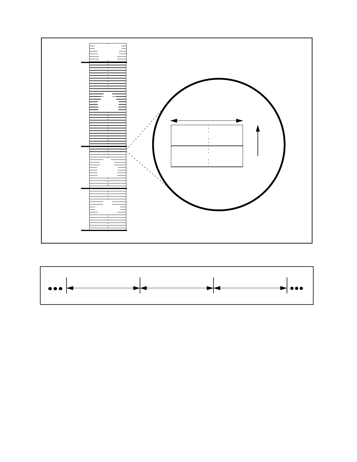
Figure 4.19 Interrupt vectors
Figure 4.20 XA Instruction Sequence Overview
Increasing
addresses
16 bits
0100h
80h
40h
0
Code Memory
32
Event
Interrupt
Vectors
16
Trap
Interrupt
Vectors
16
Exception
Vectors
Interrupt
Vectors
7 Software
Service Routine Address
Replacement PSW
Instruction n-1
Instruction n Instruction n+1