4/17/98 7-5 External Bus
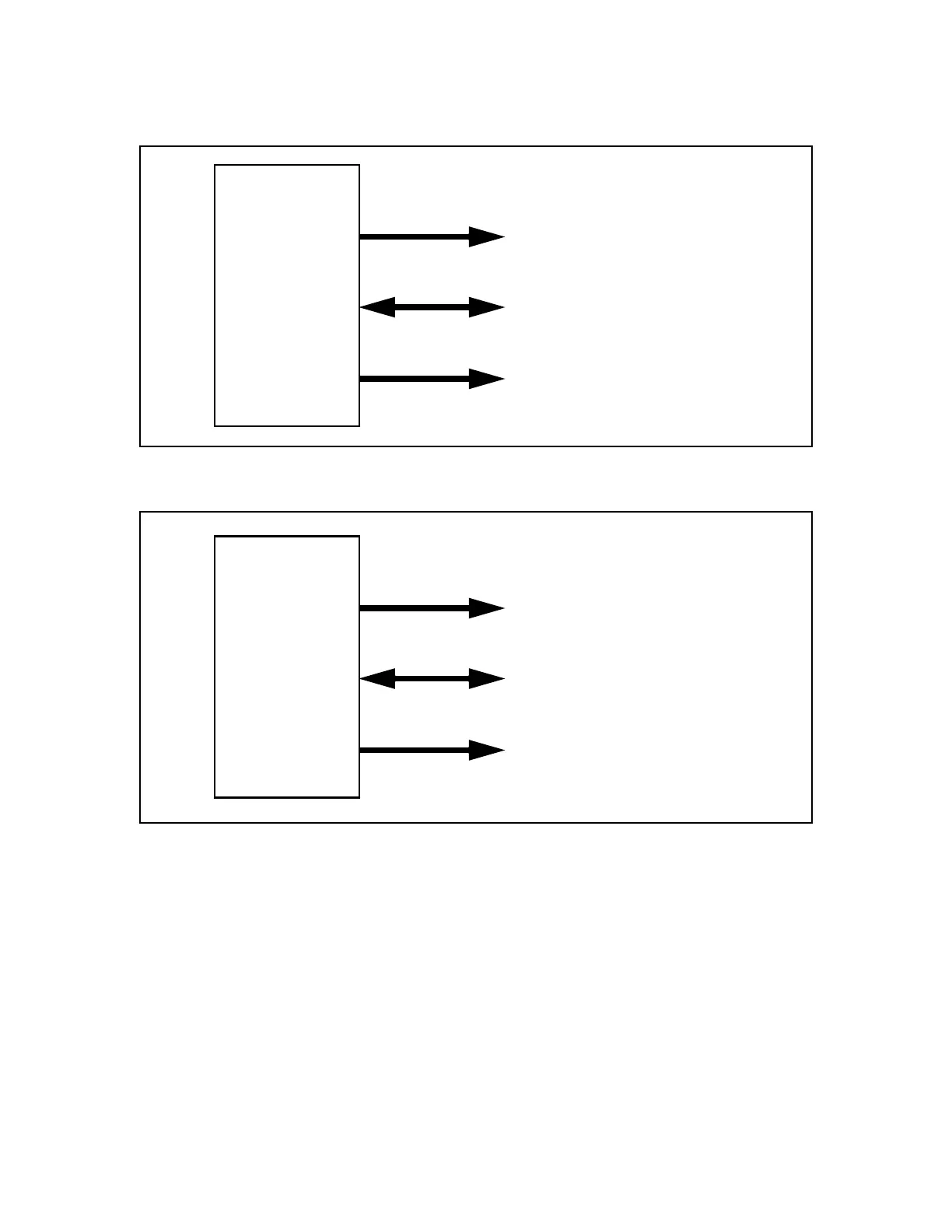
Figures 7.2 and 7.3 show the address and data functions present on XA bus related pins when
used with each available bus width.
Figure 7.2 8-Bit External Bus Configuration
Figure 7.3 16-Bit External Bus Configuration
7.2.2 Typical External Device Connections
Many possibilities exist for connecting and using external devices with the XA bus. The bus will
support EPROMs, RAMs, and other memory devices, as well as peripheral devices such as
UARTs, and parallel port expanders. The following diagrams show a generalized connection of
devices for 8-bit and 16-bit XA bus modes.
A3 - A0
A4 - A11/
D0 - D7
A12 - A23
4 low order address lines,
always driven
8 multiplexed address
and data lines
Up to 12 high order address
lines, always driven
XA
A3 - A1
A4 - A19/
D0 - D15
A20 - A23
4 low order address lines,
always driven
16 multiplexed address
and data lines
Up to 4 high order address
lines, always driven
XA