4/17/98 7-17 External Bus
7.4.2 Port Output Configurations
Standard XA I/O ports provide several different output configurations. One is the 80C51 type
quasi-bidirectional port output. Others are open drain, push-pull, and high impedance (input
only). It is important to note that the port configuration applies to a pin even if that pin is part of
the external bus. Bus pins should normally be configured to push-pull mode. Also, the port
latches for pins that are to be used as part of the external bus must be set to one (which is the
reset state). A zero in a port latch will override bus operations and force a zero on the
corresponding bus position.
The port configuration is controlled by settings in two SFRs for each port. One bit in each port
configuration register is associated with a port pin in the corresponding bit position. These port
configuration SFRs are called: PnCFGA and PnCFGB, where "n" is the port number. So, the
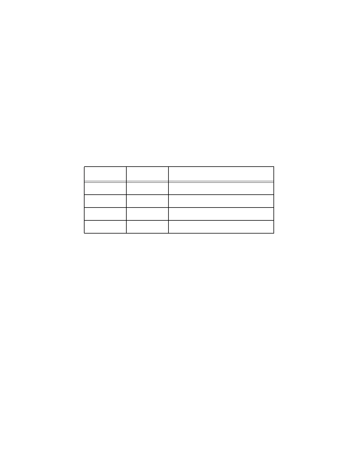
configuration registers for port 1 are named P1CFGA and P1CFGB. The table below shows the
port control bit combinations and the associated port output modes.
7.4.3 Quasi-Bidirectional Output
The default port output configuration for standard XA I/O ports is the quasi-bidirectional output
that is common on the 80C51 and most of its derivatives. This output type can be used as both an
input and output without the need to reconfigure the port. This is possible because when the port
outputs a logic high, it is weakly driven, allowing an external device to pull the pin low. When
the pin is pulled low, it is driven strongly and able to sink a fairly large current. These features
are somewhat similar to an open drain output except that there are three pullup transistors in the
quasi-bidirectional output that serve different purposes.
One of these pullups, called the "very weak" pullup, is turned on whenever the port latch for a
particular pin contains a logic 1. The very weak pullup sources a very small current that will pull
the pin high if it is left floating.
A second pullup, called the "weak" pullup, is turned on when the port latch for its associated pin
contains a logic 1 and the pin itself is a logic 1. This pullup provides the primary source current
for a pin that is outputting a 1, and can drive several TTL loads. If a pin that has a logic 1 on it is
pulled low by an external device, the weak pullup turns off, and only the very weak pullup
remains on. In order to pull the pin low under these conditions, the external device has to sink
enough current to overpower the weak pullup and pull the voltage on the port pin below its input
threshold.
Table 7.1
PnCFGB PnCFGA Port Output Mode
0 0 Open drain.
0 1 Quasi-bidirectional (default).
1 0 High impedance.
1 1 Push-pull.