3/24/97 8-1 Special Function Register Bus
8 Special Function Register Bus
The Special Function Register Bus or SFR Bus is the means by which all Special Function
Registers are connected to the XA CPU so that they may be read and written by user programs.
This includes all of the registers contained in peripherals such as Timers and UARTs, as well as
some CPU registers such as the PSW. CPU registers communicate functionally with the CPU via
direct connections, but read and write operations performed on them are routed through the SFR
bus.
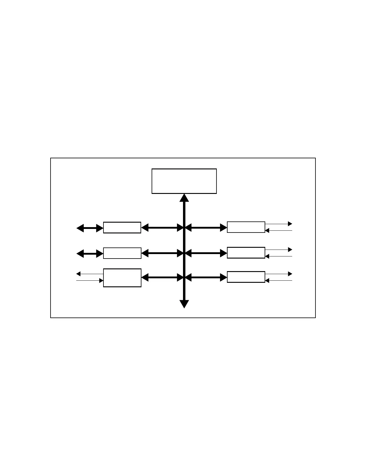
The SFR bus provides a common interface for the addition of any new functions to the XA core,
thus supplying the means for building a large and varied microcontroller derivative family. This
is illustrated in Figure 8.1.
Figure 8.1. Example of peripheral functions connected to the XA SFR bus.
8.1 Implementation and Possible Enhancements
The SFR bus interface is itself not part of the XA CPU core, but a separate functional block.
Since the SFR bus controller is a separate block, writes to SFRs may occur simultaneously with
the beginning of execution of the next instruction. If the next instruction attempts to access the
SFR bus while it is still busy, the instruction execution will stall until the SFR bus becomes
available. SFR bus read and write clocks each take 2 CPU clocks to complete. However, the
starting time of those 2 clocks has a one clock uncertainty, so the time from the SFR bus
controller receiving a request until it is completed can be either 2 or 3 clocks.
XA CPU Core
UART
Timer
I/O Port
I/O Port
SFR bus
Timer
I
2
C
Interface