80C32/80C52
Rev. G (14 Jan. 97)
15
MATRA MHS
Explanation of the AC Symbol
Each timing symbol has 5 characters. The first character
is always a “T” (stands for time). The other characters,
depending on their positions, stand for the name of a
signal or the logical status of that signal. The following
is a list of all the characters and what they stand for.
Example :
TAVLL = Time for Address Valid to ALE low.
TLLPL = Time for ALE low to PSEN
low.
A : Address.
C : Clock.
D : Input data.
H : Logic level HIGH
I : Instruction (program memory contents).
L : Logic level LOW, or ALE.
P : PSEN.
Q : Output data.
R : READ signal.
T : Time.
V : Valid.
W : WRITE signal.
X : No longer a valid logic level.
Z : Float.
AC Parameters
TA = 0 to + 70°C ; Vss = 0 V ; Vcc = 5 V ± 10 % ; F = 0 to 44 MHz
TA = 0 to +70°C ; Vss = 0 V ; 2.7 V < Vcc < 5.5 V ; F = 0 to 16 MHz
TA = –40° to + 85°C ; Vss = 0 V ; 2.7 V < Vcc < 5.5 V ; F = 0 to 16 MHz
TA = –55° + 125°C ; Vss = 0 V ; Vcc = 5 V ± 10 % ; F = 0 to 36 MHz
(Load Capacitance for PORT 0, ALE and PSEN = 100 pF ; Load Capacitance for all other outputs = 80 pF)
External Program Memory Characteristics (values in ns)
16 MHz 20 MHz 25 MHz 30 MHz 36 MHz 40 MHz 42 MHz 44 MHz
SYM-
BOL
PARAMETER min max min max min max min max min max min max min max min max
TLHLL ALE Pulse Width 110 90 70 60 50 40 35 30
TAVLL Address valid to ALE 40 30 20 15 10 9 8 7
TLLAX Address Hold After ALE 35 35 35 35 35 30 25 17
TLLIV ALE to valid instr in 185 170 130 100 80 70 65 65
TLLPL ALE to PSEN 45 40 30 25 20 15 13 12
TPLPH PSEN pulse Width 165 130 100 80 75 65 60 54
TPLIV PSEN to valid instr in 125 110 85 65 50 45 40 35
TPXIX Input instr Hold After PSEN 0 0 0 0 0 0 0 0
TPXIZ Input instr Float After PSEN 50 45 35 30 25 20 15 10
TPXAV PSEN to Address Valid 55 50 40 35 30 25 20 15
TAVIV Address to Valid instr in 230 210 170 130 90 80 75 70
TPLAZ PSEN low to Address Float 10 10 8 6 5 5 5 5
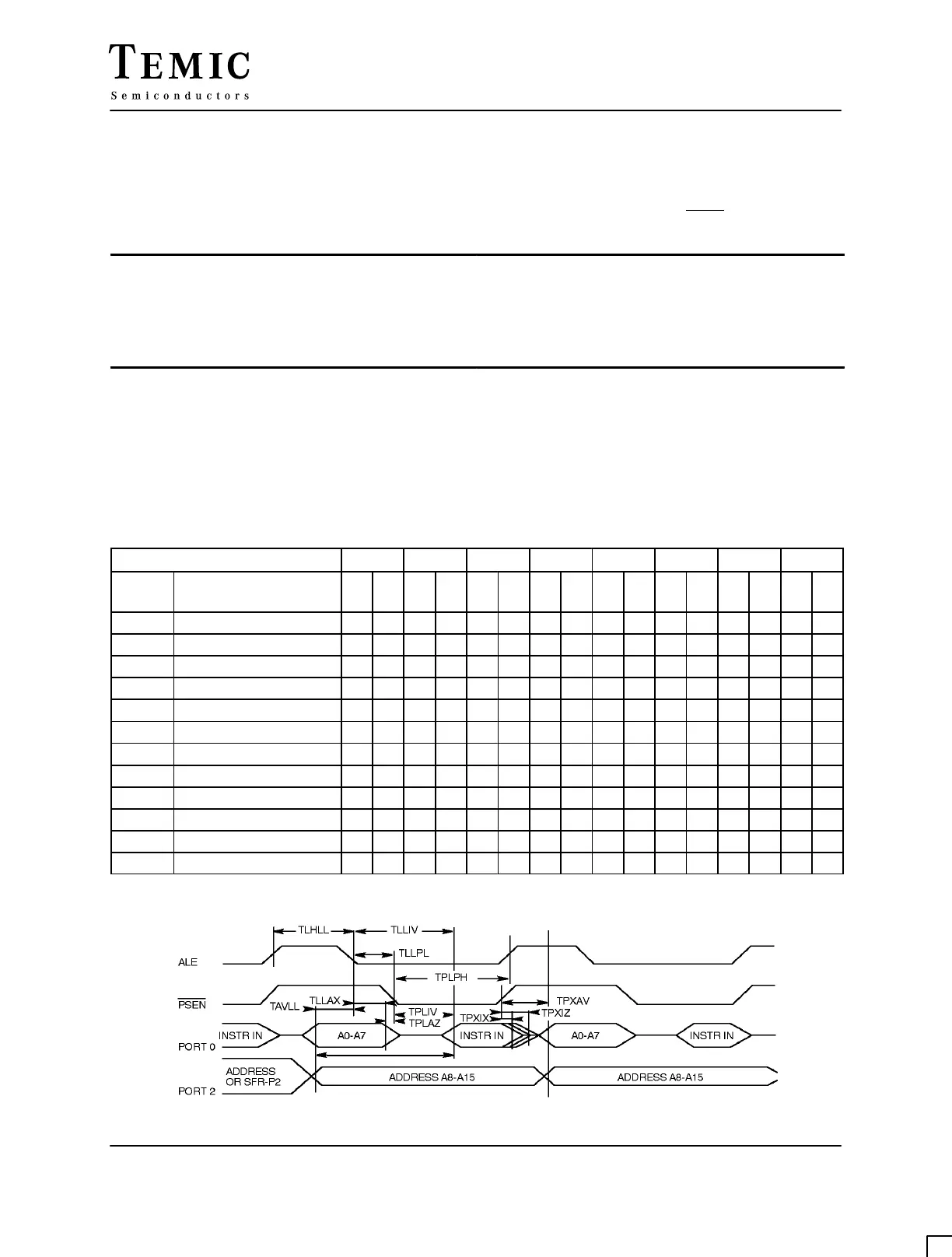
External Program Memory Read Cycle
TAVIV