4-14
This modification forces the use of software programming to
determine whether the 82C59A is a master or a slave. Bit 3
in ICW4 programs the buffered mode, and bit 2 in lCW4
determines whether it is a master or a slave.
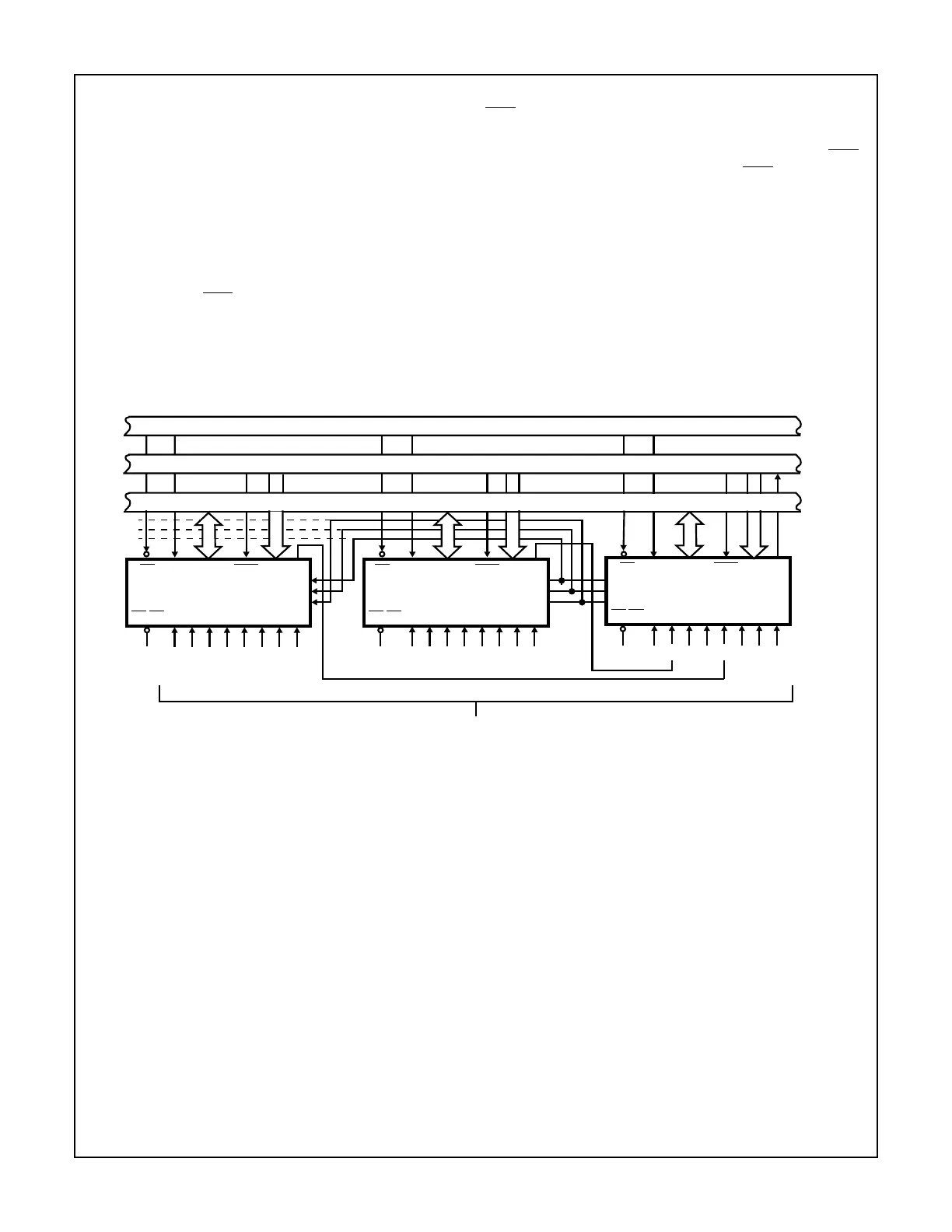
Cascade Mode
The 82C59A can be easily interconnected in a system of
one master with up to eight slaves to handle up to 64 priority
levels.
The master controls the slaves through the 3 line cascade
bus (CAS2 - 0). The cascade bus acts like chip selects to the
slaves during the
INTA sequence.
In a cascade configuration, the slave interrupt outputs (INT)
are connected to the master interrupt request inputs. When
a slave request line is activated and afterwards acknowl-
edged, the master will enable the corresponding slave to
release the device routine address during bytes 2 and 3 of
INTA. (Byte 2 only for 80C86/88/286).
The cascade bus lines are normally low and will contain the
slave address code from the leading edge of the first INTA
pulse to the trailing edge of the last
INTA pulse. Each
82C59A in the system must follow a separate initialization
sequence and can be programmed to work in a different
mode. An EOI command must be issued twice: once for the
master and once for the corresponding slave. Chip select
decoding is required to activate each 82C59A.
NOTE: Auto EOI is supported in the slave mode for the 82C59A.
The cascade lines of the Master 82C59A are activated only
for slave inputs, non-slave inputs leave the cascade line
inactive (low). Therefore, it is necessary to use a slave
address of 0 (zero) only after all other addresses are used.
FIGURE 11. CASCADING THE 82C59A
CS
82C59A
SLAVE A
CAS 0
CAS 1
CAS 2
INTA
0
D
7
- D
0
INTA
SP/EN 7 56 43210
GND
756 43210
CS
82C59A
SLAVE B
CAS 0
CAS 1
CAS 2
INTA
0
D
7
- D
0
INTA
SP/EN 7 56 43210
GND
756 43210
CS
MASTER 82C59A
CAS 0
CAS 1
CAS 2
INTA
0
D
7
- D
0
INTA
SP/EN 7 56 43210
V
CC
75421036
INT REQ
DATA BUS (8)
CONTROL BUS
ADDRESS BUS (16)
INTERRUPT REQUESTS
82C59A