3
1.3 Buffered Mode
When using the 82C59A in a large system, it may be
necessary to use bus buffers to guarantee data integrity and
guard against bus contention.
By selecting buffered mode when initializing the device, the
SP/EN pin (pin 16) will generate an enable signal for the
buffers whenever the data outputs from the 82C59A are
active. In this mode, the dual function
SP/EN pin can no
longer be used for specifying whether a particular 82C59A is
being used as a master or a slave in the system. This
specification must be made through setting the proper bit in
ICW4 during the device initialization.
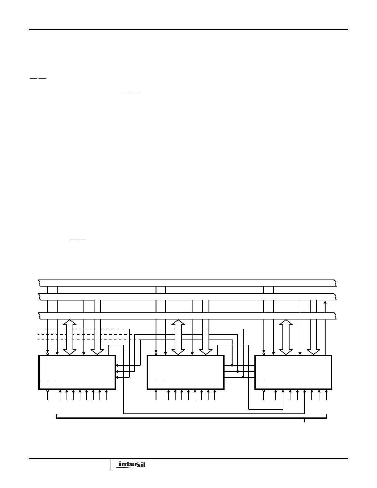
1.4 Cascade Mode
More than one 82C59A can be used in a system to expand
the number of priority interrupts to a maximum of 64 levels
without adding any additional hardware. This method of
expansion is known as “cascading”. An example of
cascading 82C59A is shown in Figure 2.
In a cascaded interrupt scheme, a single 82C59A is utilized
as the “master” interrupt controller. As many as 8 “slave”
82C59As can be connected to the IR inputs of the “master”
82C59A. Each of these slaves can support up to 8 interrupt
inputs, yielding 64 possible prioritized interrupts.
When in cascade mode, the determination of whether a
device is a master or a slave can take either of two forms.
The state of the
SP/EN pin will select “master” or “slave”
mode for a device when the buffered mode is not being
used. Should buffered mode be used, then it is necessary
that bit D2 (M/S) of ICW4 be set to indicate if the particular
82C59A is being used as a “master” or “slave” interrupt
controller in the system.
The CAS0-2 pins on the interrupt controllers serve to provide
a private bus for the cascaded 82C59As. These lines allow
the “master” to inform the slaves which is to be serviced for a
particular interrupt.
1.5 End of Interrupt (EOI)
When an interrupt is recognized and acknowledged by the
CPU, its corresponding bit will be set in the In-Service Register
(ISR). If the AEOI mode is in use, the bit will be cleared
automatically through the interrupt acknowledge signal from the
CPU. However, if AEOI is not in effect, it is the task of software
to notify the 82C59A when servicing of an interrupt is
completed. This is done by issuing an End-of-Interrupt (EOI).
There are 2 different types of EOIs that can be issued to the
device; non-specific EOI and specific EOI. In most cases,
when the device is operating in a mode that does not disturb
the fully nested mode such as Special Fully Nested Mode,
we will issue a non-specific EOI. This form of the EOI will
automatically reset the highest priority bit set in the ISR. This
is because for full nested operation, the highest priority IS bit
set is the last interrupt level acknowledged and serviced.
The “specific” EOI is used when the fully nested structure
has not been preserved. The 82C59A may not be able to
determine the last level acknowledged. Thus, the software
must specify which interrupt level is to be reset. This is done
by issuing a “specific” EOI.
FIGURE 2. CASCADING THE 82C59A
DATA BUS (8)
0
CONTROL BUS
ADDRESS BUS (16)
CS
SLAVE B
D0-7 INT
CAS 0
CAS 1
CAS 2
1234567
SP/EN
INTAA0
82C59A
GND
01234567
M0
CS
MASTER 82C59A
D0-7 INT
CAS 0
CAS 1
CAS 2
M1M2M3M4M5M6M7SP/EN
INTAA0
VCC
012
3
45
6
7
0
CS
SLAVE A
D0-7 INT
CAS 0
CAS 1
CAS 2
1234567SP/EN
INTAA0
82C59A
GND
01234567
INT
REQ
INTERRUPT REQUEST
Application Note 109