5
2.0 Initialization Control Words
The following section gives a description of the Initialization
Control Words (ICW) used for configuring the 82C59A
Interrupt controller. There are four (4) control words used for
initialization of the 82C59A. These ICWs must be
programmed in the proper sequence beginning with ICW1. If
at any time during the course of operation the configuration
of the 82C59A needs to be changed, the user must again
write out the control words to the device in their proper order.
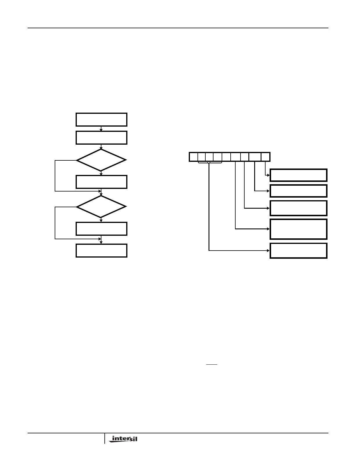
The initialization sequence is shown in Figure 3.
ICW1: The 82C59A recognizes the first Initialization Control
Word (ICW) written to it based on two criteria: (1) the A0 line
from the address bus must be a zero, and (2) the D4 bit must
be a one. If the D4 bit is set to a zero, we would be
programming either OCW2 or OCW3 (these are explained
later). The function of ICW1 is to tell the 82C59A how it is
being used in the system (i.e. Single or cascaded, edge or
level triggered interrupts etc.).
ICW2: This control word is always issued directly after
ICW1. When addressing this ICW, the A0 line from the
address bus must be a one (high). ICW2 is utilized in
providing the CPU with information on where to vector to in
memory when servicing an interrupt.
ICW3: This control word is issued only if the SNGL (D1) bit of
the ICW1 has been programmed with a zero. When
addressing this word, the A0 line from the CPU must be high
(1). This control word is for cascaded 82C59As. It allows the
master and slave 82C59As to communicate via the CAS0-2
lines. With the master, this word indicates which IR lines have
slaves connected to them. For the slave 82C59A(s), this word
indicates to which IR line on the master it is connected.
ICW4: Issuance of this ICW is selectable through the IC4
(D0) bit of ICW1. If ICW4 is to be written to the 82C59A, A0
from the CPU must be high (1) when writing to it. This word
needs to be written only when the 82C59A is operating in
modes other than the default modes. Instances when we
would want to write to ICW4 are one or more of the following:
An 80C86(80C88) processor is being used, buffered outputs
(D0 - D7) are to be used, Automatic EOIs are desired, or the
Special Fully Nested mode is to be used.
2.1 ICW1
ICW1 is the first control word that is written to the 82C59A
during the initialization process. To access this word, the
value of A0 must be a zero (0) in the addressing, and bit D4
of ICW1 must be a one (1). The format of the command word
is as follows:
D7 thru D5 - A7, A6, A5: These bits are used in the
8080/85 mode to form a portion of the low byte call address.
When using the 4 byte address interval, all 3 bits are utilized.
When using the 8 byte interval, only bits A7 and A6 are
used. Bit A5 becomes a “don’t care” bit. If using an
80C86(80C88) system, the value of these bits can be set to
either a one or zero.
D3 - LTIM:
0: The 82C59A will operate in an edge triggered mode. An
interrupt request on one of the IR lines (IR0 - IR7) is
recognized by a low to high transition on the pin. The IR
signal must remain high at least until the falling edge of the
first
INTA pulse. Subsequent interrupts on the IR pin(s) will
not occur until another low-to-high transition occurs.
1: Sets up the 82C59A to operate in the level triggered
mode. Interrupts occur when a “high” level is detected on
one or more of the IR pins. The interrupt request must be
removed from this pin before the EOI command is issued
by the CPU. Otherwise, the 82C59A will see the IR line
still in a high state, and consider this to be another
interrupt request.
READY TO ACCEPT
INTERRUPT REQUESTS
ICW4
ICW3
ICW2
ICW1
IN
IS ICW4
CASCADE
MODE
NEEDED
YES (IC4 = 1)
NO (IC4 = 0)
YES (SNGL = 0)
NO (SNGL = 1)
FIGURE 3. 82C59A INITIALIZATION SEQUENCE
A7
D7
A6
D6
A5
D5
1
D4
LTIM
D3
ADI
D2
SNGL
D1
IC4
D0
1 = ICW4 NEEDED
0 = NO ICW4 NEEDED
1 = SINGLE
0 = CASCADE MODE
CALL ADDRESS INTERVAL
1 = INTERVAL OF 4
0 = INTERVAL OF 8
1 = LEVEL TRIGGERED
0 = EDGE TRIGGERED
A7 - A5 OF INTERRUPT
VECTOR ADDRESS
(MCS-80/85 MODE ONLY)
FIGURE 4. ICW1 FORMAT
0
† A0
MODE
MODE
† A0 is an address bit, and not part of the ICW.
Application Note 109