7
D2 - ADI: Call Address Interval (for 8080/8085 use only). If
using the 82C59A in an 80C86/88 based system, the value
of this bit can be either a 0 or 1.
0: The address interval generated by the 82C59A is 8
bytes. This option provides compatibility with the RST
interrupt vectoring in 8080/8085 systems since the
vector locations are 8 bytes apart. This vector will be
combined with the values specified in bits D7 and D6 of
ICW1. The addresses generated are shown in Table 1.
1: The address interval generated by the interrupt controller
will be 4 bytes. This provides the user with a compact
jump table for 8080/8085 systems. The interrupt number is
effectively multiplied by four and combined with bits D7,
D6, and D5 to form the lower byte of the call instruction
generated and sent to the 8080 and 8085. Table 2 shows
how these addresses are generated for the various
interrupt request (IR) levels.
D1 - SNGL:
0: This tells the 82C59A that more than one 82C59A is
being used in the system, and it should expect to receive
ICW3 following ICW2. How the particular 82C59A is
being used in the system will be determined either
through ICW4 for buffered mode, or through the
SP/EN
pin for non-buffered mode operation.
1: Tells the 82C59A that it is being used alone in the
system. Therefore, there will be no need to issue ICW3
to the device.
D0 - IC4: Specifies to the 82C59A whether or not it can
expect to receive ICW4. If this device is being used in an
80C86/80C88 system, ICW4 must be issued.
0: ICW4 will not be issued. Therefore, all of the parameters
associated with ICW4 will default to the zero (0) state.
This should only be done when using the 82C59A in an
8080 or 8085 based system.
1: ICW4 will be issued to the 82C59A.
2.2 ICW2
ICW2 is the second control word that must be sent to the
82C59A. This byte is used in one of two ways by the
82C59A, depending on whether it is being used in an
8080/85 or an 80C86/88 based system.
When used in conjunction with the 8080/85 microprocessor,
the value given to this register is taken as being the high byte
of the address in the CALL instruction sent to the CPU.
In an 80C86- or 80C88-based system, ICW2 is used to send
the processor an interrupt vector. This vector is formed by
taking the value of bits D7 through D3 and combining them
with the interrupt request level to get an eight bit number.
The processor will multiply this number by four and go to that
absolute location in memory to find a starting address for the
interrupt service routine corresponding to the interrupt
request.
For example, if we set ICW2 to “00011000” and an interrupt
is recognized on IR1, the vector sent to the 80C86(80C88)
will be 00011001 (19H). The processor will then look to the
memory location 64H to find the starting address of the
corresponding interrupt service routine. It is the
responsibility of the software to provide this address in the
interrupt table.
2.3 ICW3
ICW3 is only issued when the SNGL bit in ICW1 has been
set to zero. If not set, the next word written to the 82C59A
will be interpreted as ICW4 if A0 = 1 and IC4 from ICW4 was
set to one, or it could see it as one of the Operation
Command Words based upon the state of the A0 line.
Like ICW2, this control word can be interpreted in two ways
by the 82C59A. However the interpretation of this word
depends on whether the 82C59A is being used as a
“master” or “slave” in the system. The definition of the
particular device’s role in the system is assigned through
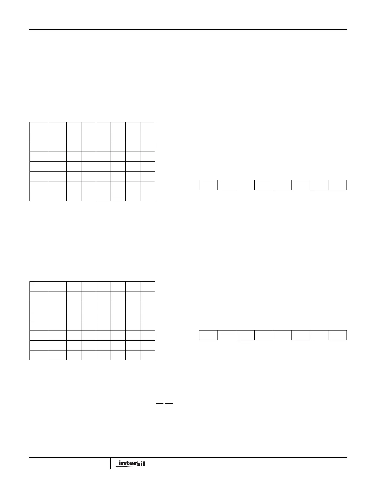
TABLE 1. ADDRESS INTERVAL (8 BYTES)
D7 D6 D5 D4 D3 D2 D1 D0
A7A6111000IR7
A7A6110000IR6
A7A6101000IR5
A7A6100000IR4
A7A6011000IR3
A7A6010000IR2
A7A6001000IR1
A7A6000000IR0
TABLE 2. ADDRESS INTERVAL (4 BYTES)
D7 D6 D5 D4 D3 D2 D1 D0
A7A6A511100IR7
A7A6A511000IR6
A7A6A510100IR5
A7A6A510000IR4
A7A6A501100IR3
A7A6A501000IR2
A7A6A500100IR1
A7A6A500000IR0
D7 D6 D5 D4 D3 D2 D1 D0
A15 A14 A13 A12 A11 A10 A9 A8
FIGURE 7. ICW2 FORMAT
D7 D6 D5 D4 D3 D2 D1 D0
A7 A6 A5 A4 A3 X X X
FIGURE 8. ICW2 FORMAT (80C86 MODE)
Application Note 109