8
ICW4 (which will be discussed later), or through the state of
the
SP/EN pin (pin 16).
82C59A AS A MASTER
If a given 82C59A is being used as a master, the eight (8)
bits in this command word are used to indicate which of the
IR lines are being driven by a slave 82C59A.
D7 THRU D0:
0: The corresponding IR line to this bit is not being driven
by a slave 82C59A. This line can however then be
connected to the interrupt output of another interrupting
device such as a UART. If there are unused bits in this
byte because not all eight of the IR lines are used, set
them to zero.
1: The corresponding IR line to this bit is being driven by a
slave 82C59A.
The bits in this command word are directly related to the IR
lines. For example, to tell the 82C59A that there is a slave
device connected to IR5 (pin 23), bit D5 of the command
word should be set to a one (1).
82C59A AS A SLAVE DEVICE
When the device is being used as a slave device, we must
use ICW3 to inform itself as to which IR line it will be
connected to in the master. Therefore, only the three (3)
least significant bits of ICW3 will be used to specify this
value.
These bits are coded as follows:
For example, if the INT output of a “slave” 82C59A is
connected to the input pin IR5 on the “master” 82C59A,
ICW3 of the “slave” would be programmed with the value
00000101b, or 05H. This informs the “slave” as to which
priority level it holds with the “master”.
D7 thru D3: These bits must be set to zeros (0) for proper
operation of the device.
2.4 ICW4
This control register is written to only when the IC4 bit is set
in ICW1. The purpose of this command word is to set up the
82C59A to operate in a mode other than the default mode of
operation. The default mode of operation is the same as if a
value of 00H were to be written to ICW4 (i.e. all bits set to
zero).
D7 thru D5: These bits must be set to zero for proper
operation.
D4-SFNM: This bit is used in the selection of the Special
Fully Nested Mode (SFNM) of operation. This mode should
only be used when multiple 82C59As are cascaded in a
system. It needs only to be programmed in the Master
82C59A in the system.
0: Special Fully Nested Mode is not selected.
1: Special Fully Nested Mode is selected.
D3 - BUF: This bit tells the 82C59A whether or not the
outputs from the data pins (D0 - D7) will be buffered. If they
are buffered, this bit will cause the
SP/EN pin to become an
output signal that can be used to control the “enable” pin on
a buffering device(s).
0: The device will be used in a non-buffered mode.
Therefore, (1) the M/S bit in ICW4 is a don’t care, and (2)
the
SP/EN pin becomes an input pin telling the device if it
is being used as a master (pin 16 = High) or a slave (pin
16 = low). For systems using a single 82C59A, the
SP/EN input should be tied high.
1: The device is used in buffered mode. An enable output
signal will be generated on pin 16, and the M/S bit will be
D7 D6 D5 D4 D3 D2 D1 D0
S7 S6 S5 S4 S3 S2 S1 S0
FIGURE 9. ICW3 FORMAT (MASTER)
D7 D6 D5 D4 D3 D2 D1 D0
00000ID2ID1ID0
FIGURE 10. ICW3 FORMAT (SLAVE)
TABLE 3. SLAVE IDENTIFICATION WITH ICW3
MASTER IR NUMBER ID2 ID1 ID0
IR7 1 1 1
IR6 1 1 0
IR5 1 0 1
IR4 1 0 0
IR3 0 1 1
IR2 0 1 0
IR1 0 0 1
IR0 0 0 0
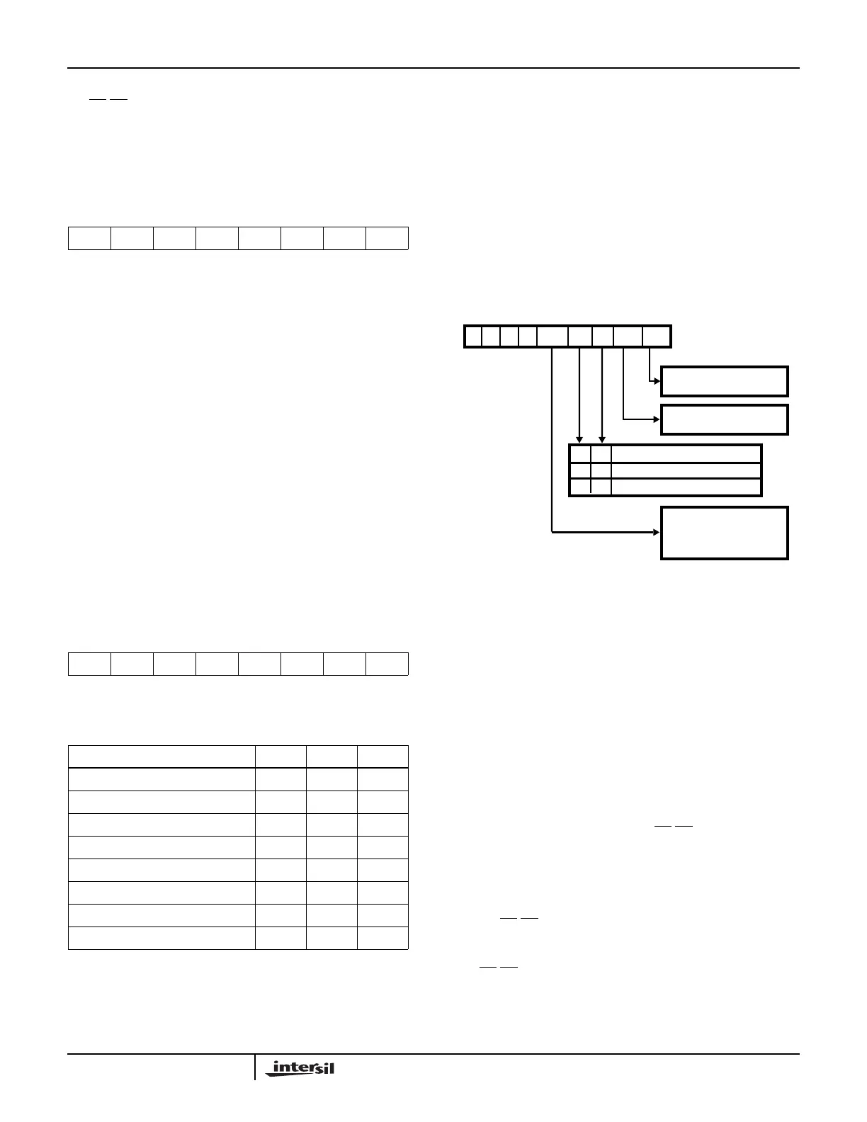
FIGURE 11. ICW4 FORMAT
0
D7
0
D6
0
D5
SFNM
D4
BUF
D3
M/S
D2
AEOI
D1
µPM
D0
1 = 8086/8088 MODE
0 = MCS-80/85 MODE
1 = AUTO EOI
0 = NORMAL EOI
1
A0
0 X
1
0
11
1 = SPECIAL FULLY
0 = NOT SPECIAL FULLY
NESTED MODE
NESTED MODE
- NON BUFFERED MODE
- BUFFERED MODE/SLAVE
- BUFFERED MODE/MASTER
Application Note 109