9
used for determining whether the particular 82C59A is a
“master” or a “slave”.
D2 - M/S: This bit is of significance only when the BUF bit is
set (BUF =1). The purpose of this bit is to determine whether
the particular 82C59A is being used as a “master” or a
“slave” in the target system.
0: The 82C59A is being used as slave.
1: The 82C59A is the master interrupt controller in the
system.
D1 - AEOI: This bit is used to tell the 82C59A to
automatically perform a non-specific End-of-Interrupt on the
trailing edge of the last Interrupt Acknowledge pulse. Users
should note that when this is selected, the nested priority
interrupt structure is lost.
0: Automatic End-of-Interrupt will not be generated.
1: Automatic End-of-Interrupt will be generated on the
trailing edge of the last Interrupt Acknowledge pulse.
D0 - µPM: This bit tells the Interrupt Controller which
microprocessor is being used in the system. An 8080/8085,
or an 80C86/80C88.
0: The 82C59A will be used in an 8080/8085 based system.
1: 82C59A to be used in the 80C86/88 mode of operation.
3.0 Operation Command Words
Once the Initialization Command Words, described in the
previous section, have been written to the 82C59A, the
device is ready to accept interrupt requests. While the
82C59A is operating, we have the ability to select various
options that will put the device in different operating modes,
by writing Operation Command Words (OCWs) to the
82C59A. These OCWs can be sent at any time after the
device has been initialized and in any order. These words
can be changed at any time as well. Note: If A0 = 0 and D4
of the command word = 1, the 82C59A will begin the ICW
initialization sequence.
There are three different OCWs for the 82C59A. Each has a
different purpose. The first control word (OCW1) is used for
masking out interrupt lines that are to be inactive or ignored
during operation. OCW2 is used to select from various
priority resolution algorithms in the device. Finally, OCW3 is
used for (1) controlling the Special Mask Mode, and (2)
telling the 82C59A which Register will be read on the next
RD pulse; the ISR (In-service Register) or the IRR (Interrupt
Request Register).
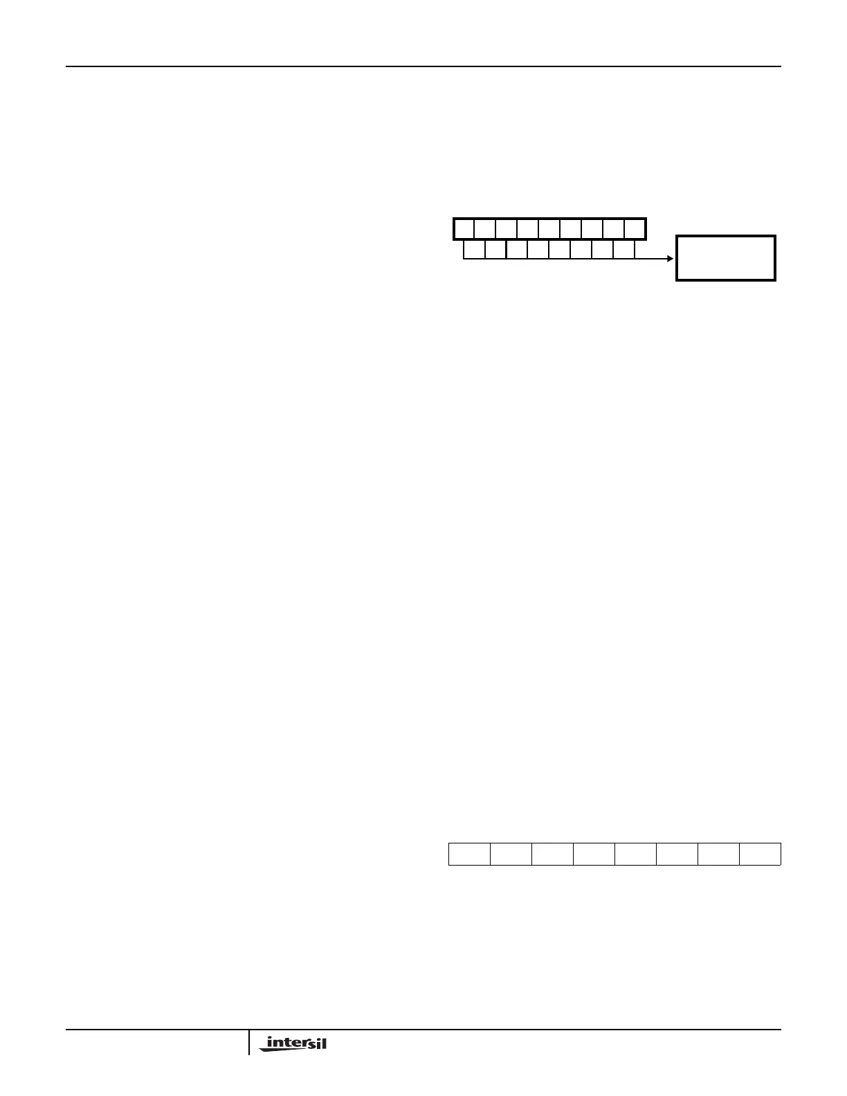
3.1 OCW1
This control word is used to set or clear the masking of the
eight (8) interrupt lines input to the 82C59A. This control
word performs this function via the Interrupt Mask Register
(IMR). In it’s initial state, the value of this register is 00H. In
other words, all of the interrupt lines are enabled. Therefore,
we need only write this control word when we wish to disable
specific interrupt lines.
A direct mapping occurs between the bits in this control word
and the actual interrupt pins on the device. For example bit 7
(D7) controls interrupt line IR7 (pin 25), bit 6 controls IR6,
and so on.
Even though the user can mask off any of the IR lines, any
interrupt occurring during that time will not be lost. The
request for an interrupt is retained in the IRR; therefore when
that IR is unmasked by issuing a new mask value to OCW1,
the interrupt will be generated when it becomes the highest
requesting priority.
D7 THRU D0:
0: When any of the bits in the control word are reset (0), the
corresponding interrupt is enabled.
1: By setting a bit(s) to a one in the control word, the
corresponding interrupt line(s) is disabled.
For example, if the value 34H (00110100b) were written to
OCW1, interrupts would be disabled from being serviced on
lines IR2, IR4, and IR5.
3.2 OCW2
In ICW4 bit D1 was used to specify whether the 82C59A
should wait for an EOI (End of Interrupt) from the CPU, or
generate its own EOI (Automatic EOI). If bit D1 of ICW4 had
been programmed to be zero, OCW2 would be used for
sending the EOI to the 82C59A. Conversely, if this bit had
been set to a one, OCW2 would be used for specifying
whether or not the 82C59A should perform a priority rotation
on the interrupts when the AEOI is detected.
OCW2 has several EOI options. The EOI issued can be
either specific or non-specific. For each of these EOIs, the
user can specify whether or not priority rotation should be
performed.
R, SL, AND EOI:
These three bits are used for specifying how the device
should handle AEOIs, or for issuing one of several different
EOIs. They are programmed as shown in the following table.
D7 D6 D5 D4 D3 D2 D1 D0
R SL EOI 0 0 L2 L1 L0
FIGURE 13.
FIGURE 12. OCW1 FORMAT
M7
D7
M6
D6
M5
D5
M4
D4
M3
D3
M2
D2
M1
D1
M0
D0
1 = MASK SET
1
A0
0 = MASK RESET
INTERRUPT MASK
Application Note 109