10
L2, L1, AND L0:
These three bits of the control word are used in conjunction
with the issuance of specific EOIs or when specifically
establishing a different priority structure. The bits tell the
82C59A which interrupt level is to be acted upon. Therefore,
the software needs to know which interrupt is being serviced
by the 82C59A
3.3 OCW3
There are two main functions that OCW3 controls: (1)
Interrupt Status, and (2) Interrupt Masking. Interrupt status
can be checked by looking at the ISR or IRR registers, or by
issuing a Poll Command to manually identify the highest
priority interrupt requesting service.
D7: Must be set to zero for proper operation of the 82C59A.
D6 - ESMM: Enable Special Mask Mode - The ESMM bit
when enabled allows the SMM bit to set or clear the Special
Mask Mode. When disabled this bit causes the SMM bit to
have no effect on the 82C59A.
0: Disables the effect of the SMM bit.
1: Enable the SMM bit to control the Special Mask Mode.
D5 - SMM: Special Mask Mode - The SMM bit is used to
enable or disable the Special Mask Mode. This bit will only
affect the 82C59A when the ESMM bit is set to 1.
0: Disable the Special Mask Mode.
1: Put the 82C59A into the Special Mask Mode.
D4, D3: These bits are used to differentiate between
OCW2, OCW3, and ICW1. To properly select OCW3, D4
must be set to zero and D3 must be set to one.
D2 - P: Poll Command - This bit is used to issue the poll
command to the 82C59A. The next read of the 82C59A will
cause a poll word to be returned which tells if an interrupt is
pending, and if so, which is the highest requesting level.
NOTE: The poll command must be issued each time the poll opera-
tion is desired.
0: No poll command issued to the 82C59A.
1: Issue the poll command.
D1 - RR: Read Register - This bit is used to execute the
“read register” command. When this bit is set, the 82C59A
will look at the RIS bit to determine whether the ISR or IRR
register is to be read. When issuing this command, the next
instruction executed by the CPU should be an input from this
same port to get the contents of the specified register.
0: No “Read Register” command will be performed.
1: The next input instruction by the CPU will read either
the contents of the ISR or the IRR as specified by the
RIS bit.
D0 - RIS: This bit is used in conjunction with the RR bit to
select which register is to be read when the “Read Register”
command is issued.
0: The next input instruction will read the contents of the
Interrupt Request Register (IRR).
1: The next input instruction will read the contents of the In-
Service Register (ISR).
The two registers that can be accessed through the Read
Register command are used to determine which interrupts
are requesting service, and which one(s) are currently being
serviced.
The IRR bits get set when corresponding Interrupt requests
are received. For instance, when IR4 is detected, bit D4 of
the IRR will get set. When an interrupt acknowledge comes
back from the CPU, the priority resolution logic will
determine which interrupt request will be serviced. The
corresponding bit in the In-service Register (ISR) will then
be set. Clearing of the correct bits in the ISR occurs through
out use of the AEOI, or by issuing an EOI to the device.
TABLE 4. ROTATE AND EOI MODES
R SL EOI
0 0 1 Non-specific EOI command
0 1 1 *Specific EOI command
1 0 1 Rotate on non-specific EOI command
1 0 0 Rotate in Automatic EOI mode (set)
0 0 0 Rotate in Automatic EOI mode (clear)
1 1 1 *Rotate on specific EOI command
1 1 0 *Set priority command
0 1 0 No operation
* L0 - L2 are used.
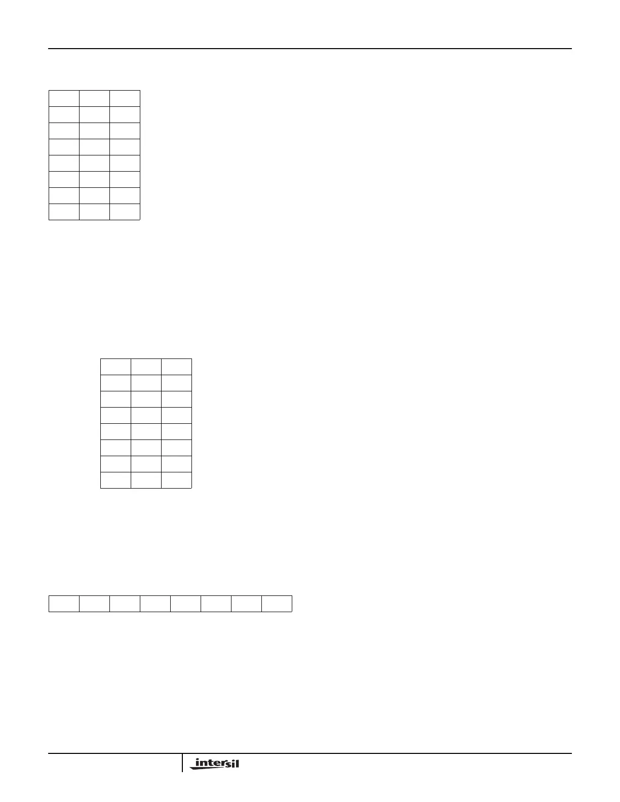
TABLE 5. INTERRUPT LEVEL TO ACT UPON
L2 L1 L0
0 0 0 IR level 0
0 0 1 IR level 1
0 1 0 IR level 2
0 1 1 IR level 3
1 0 0 IR level 4
1 0 1 IR level 5
1 1 0 IR level 6
1 1 1 IR level 7
D7 D6 D5 D4 D3 D2 D1 D0
0 ESMM SMM 0 1 P RR RIS
FIGURE 14.
Application Note 109