13
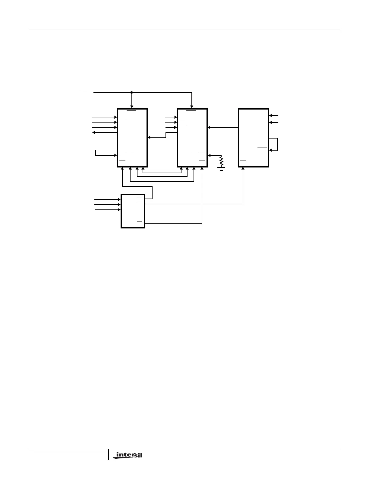
5.2 Example 2: Cascaded 82C59As
Example 2 illustrates how we can use multiple 82C59As in
Cascade Mode. Figure 17 shows the interconnections
between the master and slave interrupt controllers. In this
example, only one interrupt can occur. This is generated by
the 82C52 UART. Except for the fact that this system is
configured with a Master-Slave interrupt scheme, it is the
same as that in Example 1.
FIGURE 17. EXAMPLE 2: CASCADED 82C59As
C
B
A
Y6
DECODER
Y5
AD2
AD3
AD4
Y0
IR5
SP/EN
A0
CS
INTA
RD
WR
INT
GND
2kΩ
AD0AD0
VCC
210
CAS
MASTER
82C59A
INTA
IR2
SP/EN
A0
CS
INTA
RD
WR
INT
01 2
CAS
SLAVE
82C59A
A0
82C52
INTR
DR
DSR
CS
A1
AD0
AD1
Application Note 109