12
5.0 Programming the 82C59A
As described earlier, there are two different types of
command words that are used for controlling 82C59A
operation; the Initialization Command Words (ICWs) and the
Operation Command Words (OCWs). To properly program
the 82C59A, it is essential that the ICWs be written first.
When writing the ICWs to the 82C59A, they must be written
in the following sequence:
1. Write ICW1 to the 82C59A, A0 = 0.
2. Write ICW2 to the 82C59A, A0 = 1.
3. If using cascaded 82C59As in system, write ICW3 to the
82C59A, A0 = 1.
4. If IC4 bit was set in ICW1, write ICW4 to the 82C59A.
NOTE: When using multiple 82C59As in the system (cascaded),
each one must be initialized following the above sequence.
Once the 82C59A(s) has been configured through the ICWs,
the OCWs can be used to select from the various operation
mode options. These include: masking of interrupt lines,
selection of priority rotation, issuance of EOIs, reading of the
ISR and/or IRR etc. These OCWs can be written to the
82C59A at any time during operation of the 82C59A. The
various command words are identified by the state of
selected bits in the words, rather than by the sequence that
they are written to the 82C59A; as with the ICWs. Therefore,
it is imperative that the fixed bit values in the command
words be written as such to insure proper operation of the
device(s).
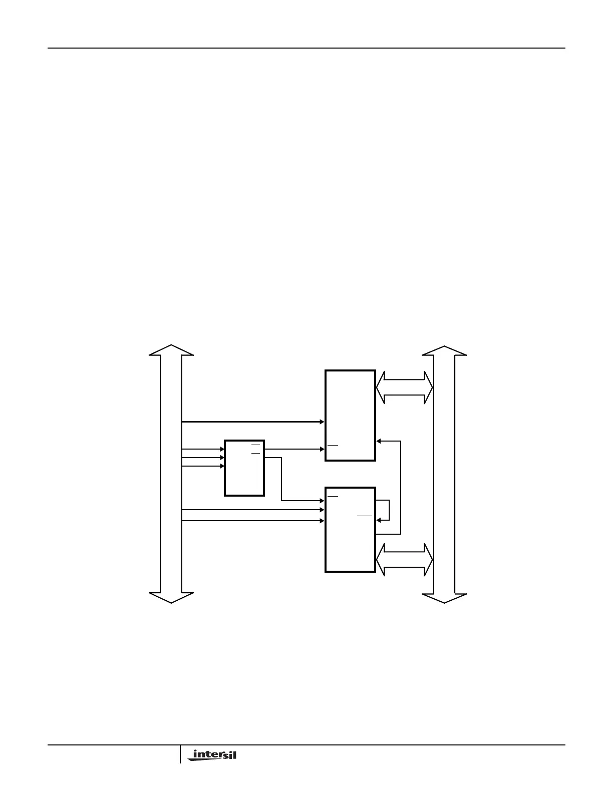
5.1 Example 1: Single 82C59A
In Example 1, we are using a single 82C59A in a system to
handle the interrupts caused by an 82C52 Programmable
UART. The system is driven using a 80C86 microprocessor.
The system configuration is shown in Figure 16.
Interrupts are initiated by the 82C52 anytime it receives data
on its Serial Data in pin (SDI), or when it is ready to transmit
more data via its Serial Data Out pin (SDO).
FIGURE 16. EXAMPLE 1: SINGLE 82C59A
AD0
IR2
A0
CS
D0 - D7
C
B
A
Y6
DECODER
82C59A
80C86
ADDRESS
BUS
AD2
AD3
AD4
AD0
Y4
AD1
80C86
DATA
BUS
INTR
A0
CS
82C52
A1
DR
DSR
D0 - D7
Application Note 109