Before the hardware connection is complete, we must also connect the other pins of the timer.
The data sheet of the 8253 gives the purpose of these pins. Simplest are the data bus pins: D0-
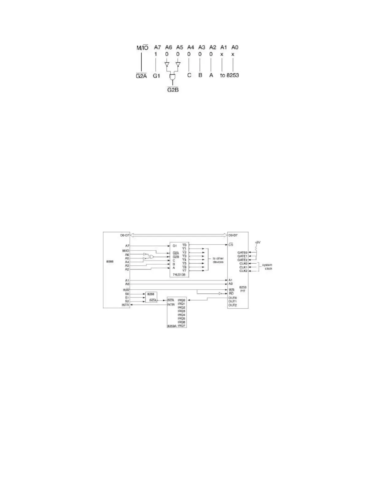
D7. These obviously must connect to the corresponding lines of the data bus. The Vcc pin is for
power, so it must connect to the power supply of the computer. The GND pin is for electrical
ground. This leaves the RD#, WR#, CLKn, GATEn and OUTn pins. RD# and WR# are for
enabling reading from the timer's ports and writing to them, respectively. The CPU has a single
pin, R/W#, so to get the proper behavior, we must "split" this signal. We will invert the R/W#
signal to feed to the RD# pin of the 8253 and connect the R/W# signal directly (not inverted) to
the WR# pin. The CLKn pins receive the input clock pulse, so we can connect these to the
system clock to provide input for the timer. The OUTn pins provide the output signal from the
timer. Since we will use the timer to generate timer interrupts for the operating system, we will
connect these pins to the interrupt controller. Finally, the GATEn pins serve to individually
enable or disable the three counters on the 8253 chip. Since we want these to be permanently
enabled, we can connect them to a pullup resistor to keep them always at +5 volts. The figure
below shows the completed connection diagram.
The Interrupt Service Routine
The exact nature of the interrupt service routine and the tasks that it performs depend on the the
device itself and the job that it must do. You have already seen an introduction to interrupt
handlers for peripheral devices and you know how to install their starting addresses in the
exception vector table. You also know that exception and interrupt handlers must end with the
IRET instruction. Beyond those general considerations, a few more points deserve special
mention. It is important in many instances to disable interrupts before installing a handler's
address in the Exception Vector, because it is essential that the full address (both segment and
offset) are both correct before the exception of interrupt occurs. If the service routine is an
exception handler, this may not be a critical concern, although it can be. For example, consider
what would happen in a multitasking operating system if the program installing the handler