CHAPTER 9
Optical Protection Switch (OPS)
•
OPS Overview on page 211
•
OPS Equipment on page 212
•
OPS Specifications on page 213
•
OPS AC power unit Specifications on page 214
OPS Overview
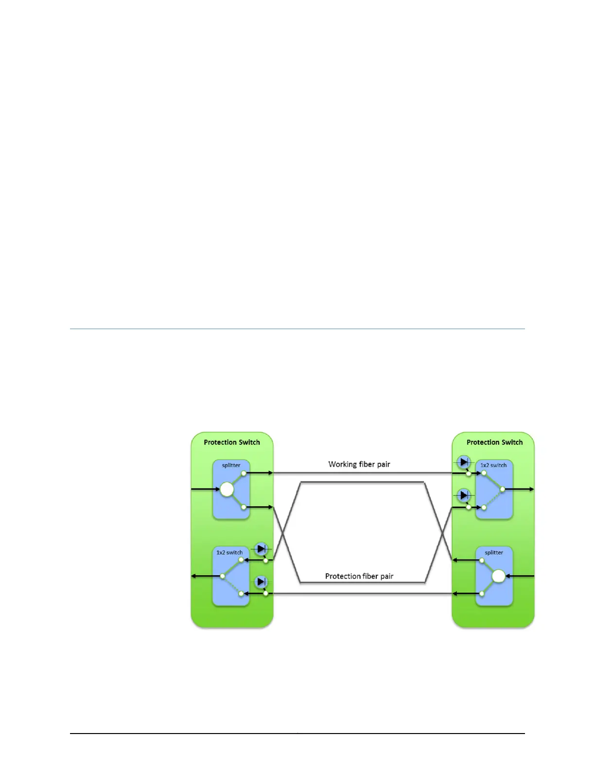
The Optical Protection Switch provides 1+1 optical protection switching in a 1RU form
factor. When used with diversely routed fiber pairs, the Optical Protection Switch can
protect against fiber plant failure by switching to the good fiber pair. An optical splitter
at the head end broadcasts the DWDM wavelengths on both fibers and a 1x2 optical
switch at the tail end selects the surviving signal. Optical photo detectors at the switch
end monitor power levels that are used for switching decisions.
Each chassis contains two OPS power cards for redundant power, an OPS system control
card, a passive cooling unit, and slots for up to four OPS 1+1 module pluggables. Each
OPS 1+1 module pluggable contains two independent switches. A fully populated chassis
can support eight 1+1 protected links.
211Copyright © 2019, Juniper Networks, Inc.

 Loading...


