Management of the OPS is performed using a Web GUI, reachable through the local
Ethernet ports on the OPS system control card. The OPS can also be discovered and
monitored by the proNX Service Manager.
OPS Equipment
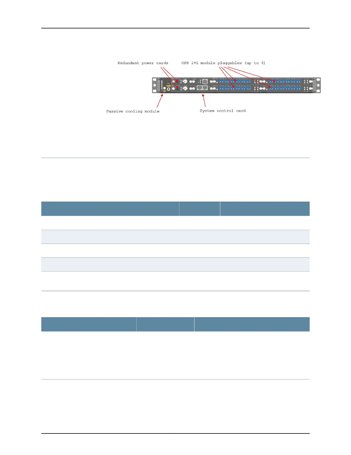
The Optical Protection Switch is ordered as a kit, which includes the chassis, redundant
DC power, a control card, a switch card, and mounting brackets and cables
(Table 80 on page 212):
Table 80: Optical Protection Switch Kit - Dual Switch Card (BT7A39AS)
Component PECQuantity in KitComponent
BT7A39AA1OPS 1RU chassis
BT7A39AB1OPS 1+1 module pluggable
BT7A39AC1OPS system control card
BT7A39AP2OPS power card
BT7A39AD1OPS accessories kit (includes mounting brackets and DC power
cables)
Equipment for AC operation is ordered separately (Table 81 on page 212):
Table 81: AC Power and Power Cables
NotesComponent PECComponent
The OPS AC power unit takes AC input and provides
DC output to the OPS power card (BT7A39AP) over
a DC power cable (included). The AC power cable is
not included and must be ordered separately.
Two units are required per OPS (one unit for each
OPS power card (BT7A39AP)).
BT7A39AEOPS AC power unit
Copyright © 2019, Juniper Networks, Inc.212
BTI7800 Series Hardware Overview and Installation Guide

 Loading...


