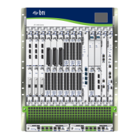
Replacing the Fuses on a BTI7814 AC PEM
Use this procedure to remove and replace a fuse on an AC Power Entry Module (AC PEM)
on the BTI7814 chassis.
Changing a fuse on the AC PEM must be performed with the power off to some rectifiers.
If the blown fuse is located in the top fuse array, then the rectifiers in Slot 1 and Slot 2
must be disconnected from their power source. If the blown fuse is located in the bottom
fuse array, then the rectifiers in Slot 3 and Slot 4 must be disconnected from their power
source. The slots are numbered 1 to 4 from top to bottom.
WARNING: Ensure that you are familiar with the safety and electrical warnings
described in “BTI7814 Field-Replaceable Units (FRUs)” on page 179.
NOTE: The cause of the blown fuse must be understood and the problem
rectified prior to changing the fuse.
Tools Required
•
Number 2 Phillips screwdriver
1. Identify the slot for which the fuse has blown.
2. Look at the fuse location diagram to determine the fuse array that contains the blown
fuse.
The fuses are divided into two fuse arrays. The top fuse array protects the DC output
of the A feed, and is located behind the AC PEM in Slot 2. The bottom fuse array
protects the DC output of the B feed, and is located behind the AC PEM in Slot 3.
185Copyright © 2019, Juniper Networks, Inc.
Chapter 7: BTI7800 Series Field Replaceable Units (FRUs)

 Loading...


